Assembly of an Anet A8 3D printer

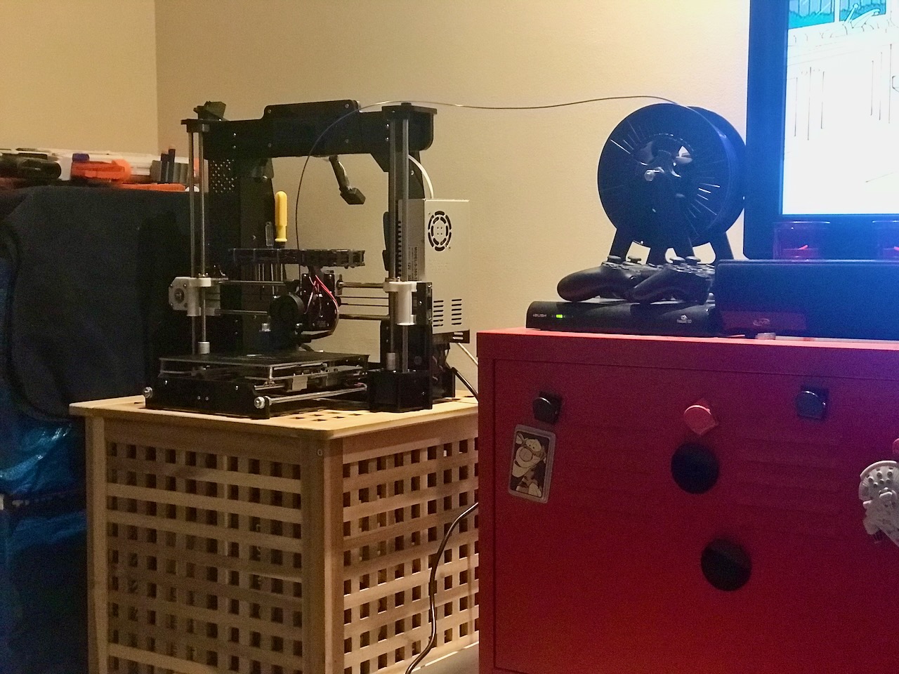
Table of contents
Intro
This project was to assemble a cheap 3D printer with the premise to eventually make it better by upgrading components and 3D printing improved parts.
Assembly
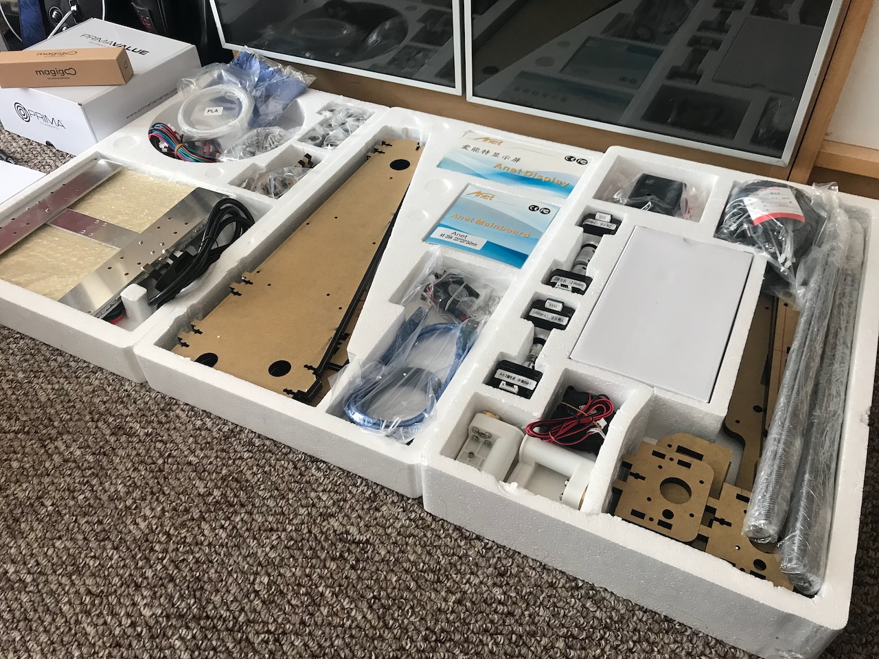
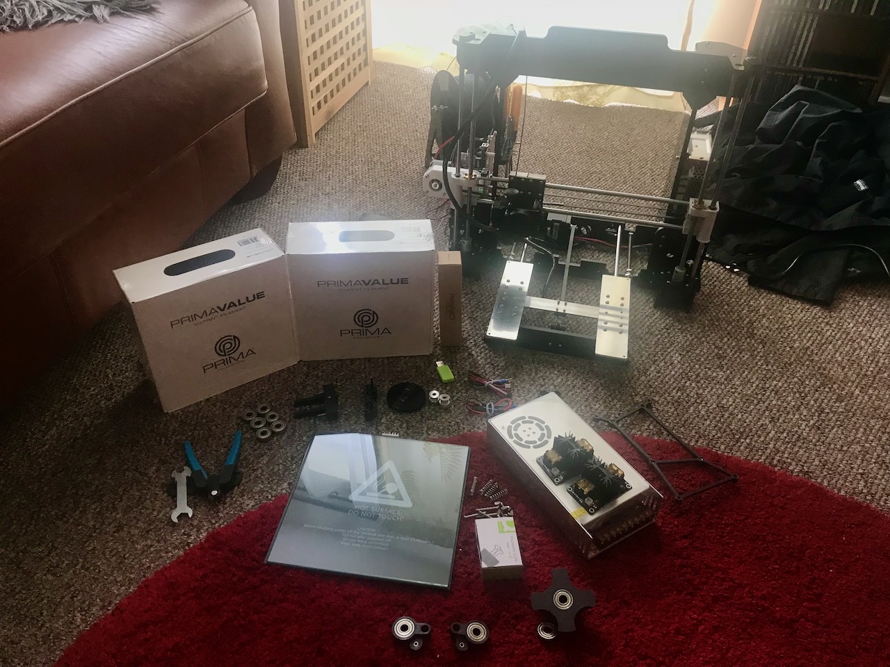
The kit comes nicely packed in these polystyrene trays keeping things nice and protected.
Frame
✅ Assembly Step 1
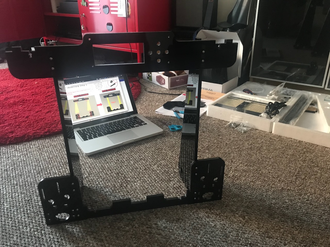
The top and bottom support plates get fixed to the side support plates making up the main part of the frame.
Parts Used
| Item | Quantity |
|---|---|
| Bottom support plate | 1 |
| Top support plate | 1 |
| Side support plate | 2 |
| M3x18 Screw | 12 |
| M3 Nut | 12 |
✅ Assembly Step 2
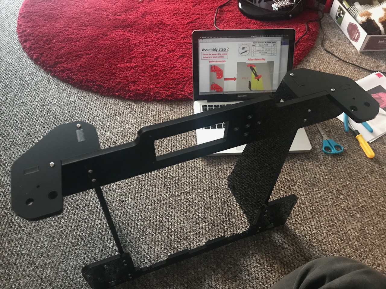
And finally the support plate lock plates tie them together.
Parts Used
| Item | Quantity |
|---|---|
| Step 1 | 1 |
| Support plate lock plate | 2 |
| M3x18 Screw | 4 |
| M3 Nut | 4 |
Y Axis
✅ Assembly Step 3
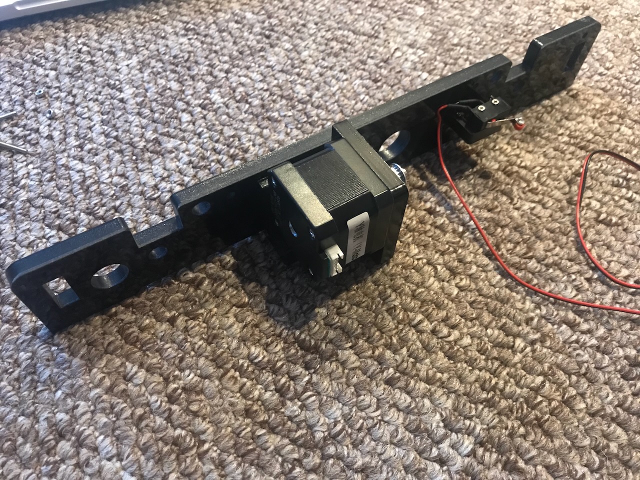
The Y axis motor is secured to the back plate by the Y axis motor fixed plate and the Y limit switch is fixed into place with the Y axis limit switch fixed plate.
Parts Used
| Item | Quantity |
|---|---|
| Back plate | 1 |
| Y axis motor | 1 |
| Y axis motor support | 1 |
| Y axis motor fixed plate | 1 |
| Y axis Limit switch fixed plate | 1 |
| Y axis Limit Switch C 70CM | 1 |
| M3x12 Screw | 4 |
| M2x12 Screw | 2 |
| M3x18 Screw | 4 |
| M3 Nut | 4 |
✅ Assembly Step 4
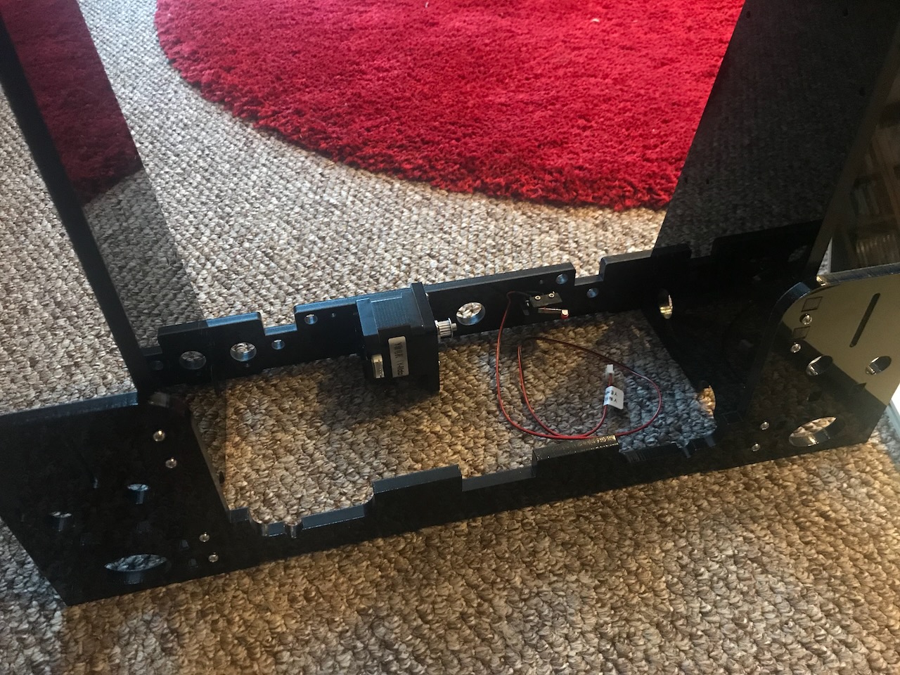
The back plate is then attached to the rear of the frame.
Parts Used
✅ Assembly Step 5
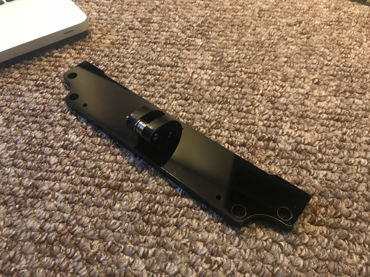
The Y axis bearing support is attached to the front plate.
Parts Used
| Item | Quantity |
|---|---|
| Y axis belt bearing support | 1 |
| Front plate | 1 |
| M3x18 Screw | 2 |
| M3 Nut | 2 |
✅ Assembly Step 6
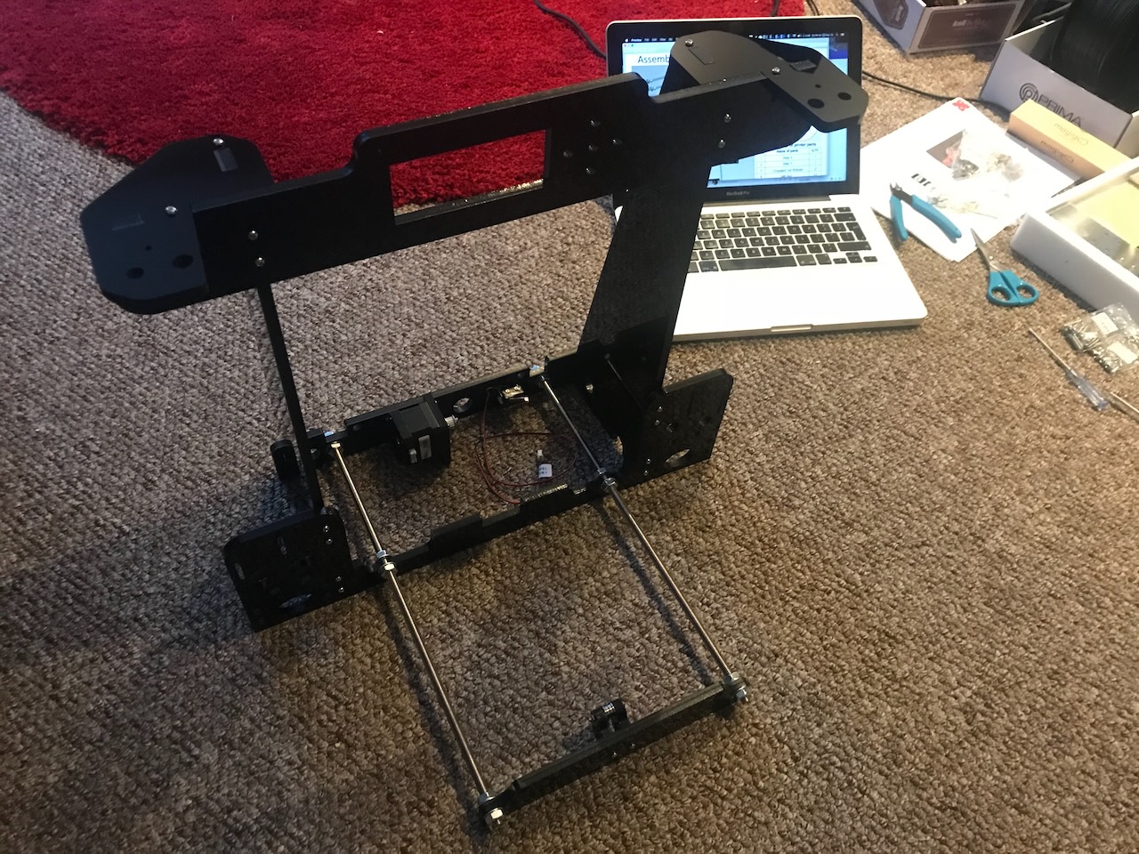
The front plate is then attached to the main frame using the 400mm M8 threaded rods and 12 M8 nuts and washers.
Parts Used
✅ Assembly Step 7
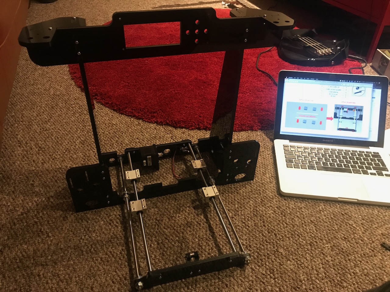
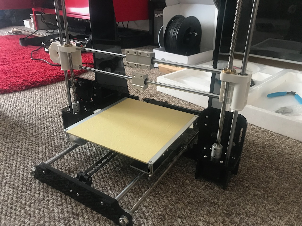
2 linear bearing blocks are threaded onto 2 of the 380mm smooth rods and then affixed next to the threaded rods. These are held in place with 4 guide rod back up plates.
Parts Used
| Item | Quantity |
|---|---|
| Step 6 | 1 |
| Y axis Guide rod | 2 |
| Guide rod back up plate | 4 |
| Linear bearing | 4 |
| M3x18 Screw | 4 |
| M3 Nut | 12 |
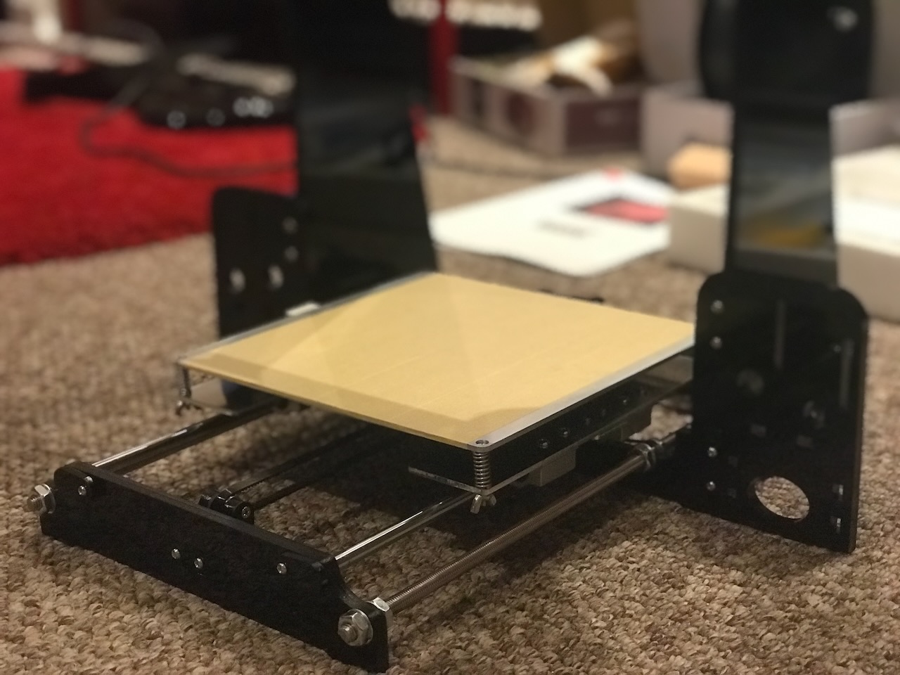
Heated Bed
✅ Assembly Step 8
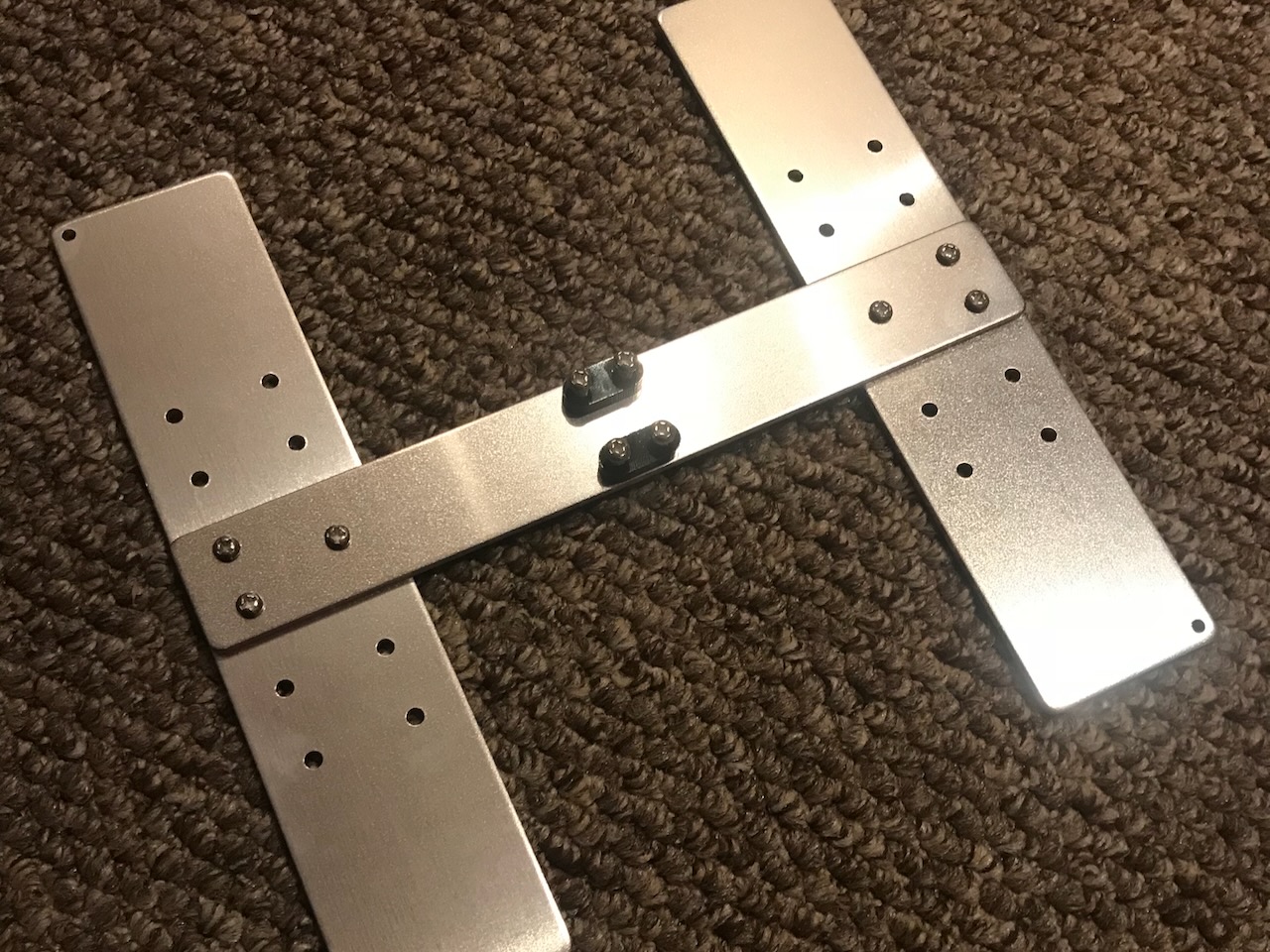
Two Y axis fixation clamps are loosely screwed to the hot bed fixed aluminium plate, these will hold the ends of the belt later.
Note
The belt fixation clamps are attached on the opposite side of the hot bed fixed aluminium plate here compared to the manual. I did this intentially as this lowers the attachment point of the belt allowing the belts to be more parallel than on the stock build.
Parts Used
| Item | Quantity |
|---|---|
| Hot bed fixed aluminium plate | 1 |
| Y axis belt fixation clamp | 2 |
| M4x14 Screw | 4 |
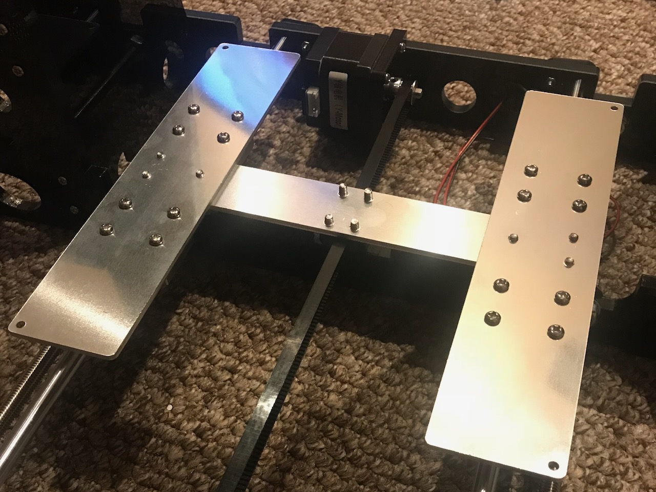
✅ Assembly Step 9
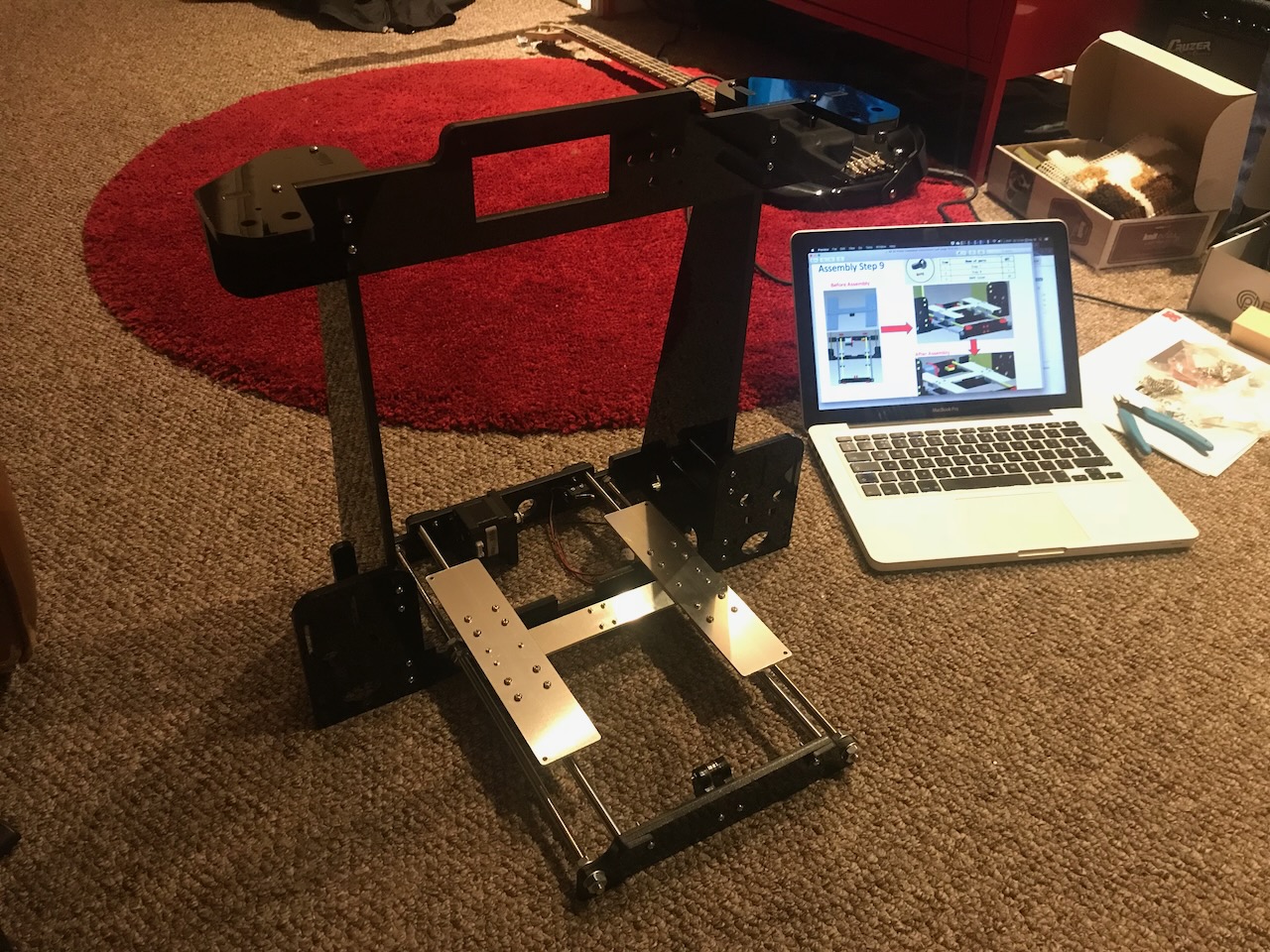
The hot bed aluminium plate is then attached to the linear bearing blocks.
Parts Used
✅ Assembly Step 10
The Y axis belt is then installed and the carriage is moved back and forth along the rails to ensure the travel is smooth.
Parts Used
| Item | Quantity |
|---|---|
| Belt | 1 |
✅ Assembly Step 11
The heated bed is then attached to the hot bed aluminium plate with 4 springs and wing nuts to allow the bed to be levelled.
Tip
I added M3 Nuts here before adding the springs to stop the screws rotating in the countersink of the heated bed when adjusting the bed with the wing nuts.
Parts Used
| Item | Quantity |
|---|---|
| Step 9 | 1 |
| Hot bed | 1 |
| M3x30 Screw | 4 |
| M3 Nut | 4 |
| Spring | 4 |
| M3 wing nut | 4 |
Z Axis
✅ Assembly Step 12
The Z axis motors are attached to the Z axis motor fixed plates and then attached to the frame with the 4 Z axis support plates. The Z axis limit switch is then affixed to the frame with the Z axis limit switch fixed plate.
Parts Used
| Item | Quantity |
|---|---|
| Step 10 | 1 |
| Z axis motor | 2 |
| Z axis motor fixed plate | 2 |
| Z axis motor support plate | 4 |
| Z axis Limit switch fixed plate | 2 |
| Z axis Limit switch A 20CM | 1 |
| M3x18 Screw | 10 |
| M3 Nut | 12 |
| M3x12 Screw | 8 |
| M3x25 Screw | 2 |
✅ Assembly Step 13 & 14
The Z axis nut supports are each added to the last two 380mm smooth rods and then threaded through the support plate lock plates at the top of the frame. These are held in place with the two remaining guide rod back up plates.
Parts Used
| Item | Quantity |
|---|---|
| Step 11 | 1 |
| Step 12 | 1 |
| Right Z axis nut support | 1 |
| Guide rod back up plate | 2 |
| Z axis Guide rod 380mm | 2 |
| M3x18 Screw | 2 |
| M3 Nut | 2 |
| M2.5x10 Screw | 2 |
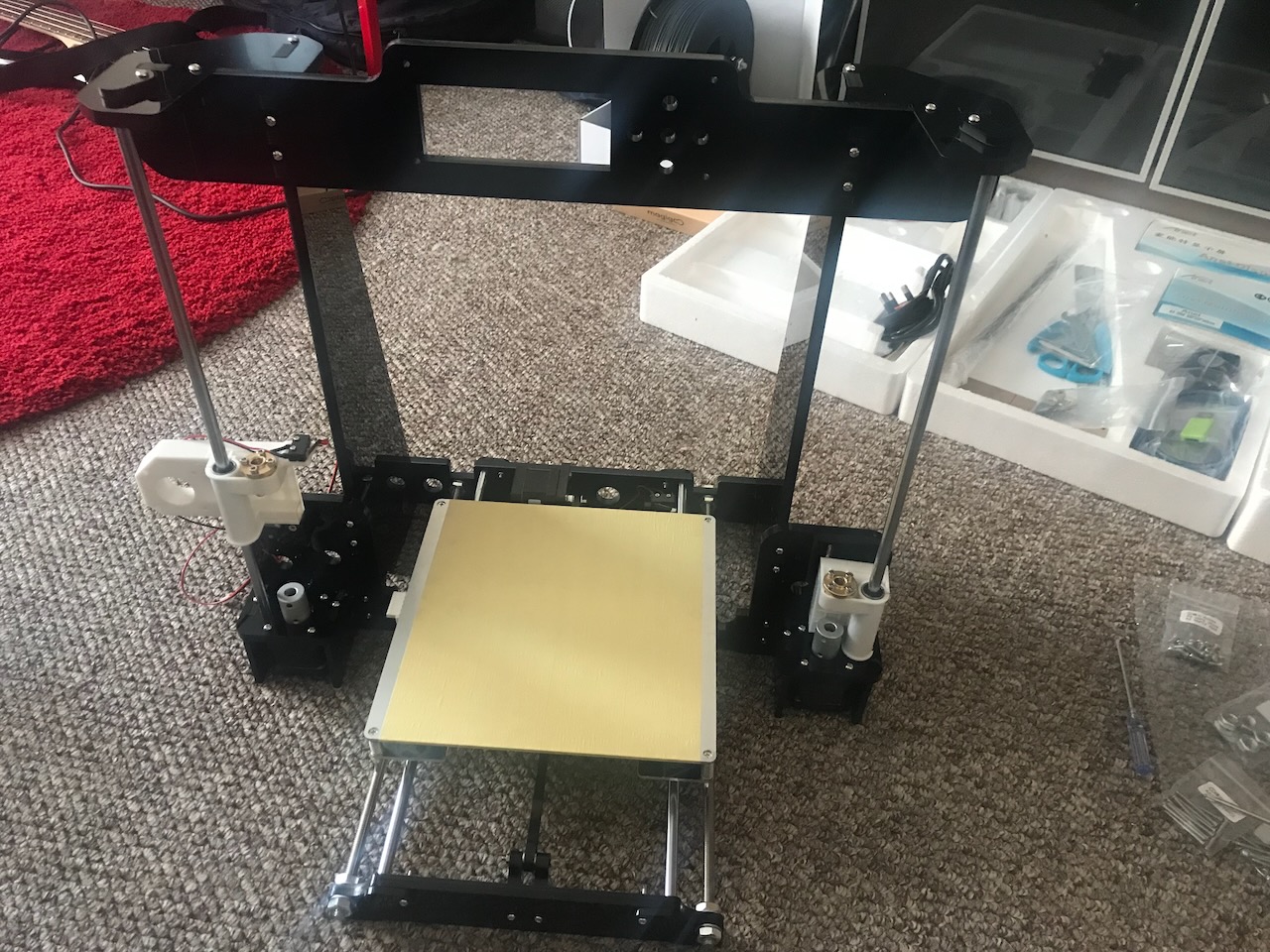
✅ Assembly Step 15
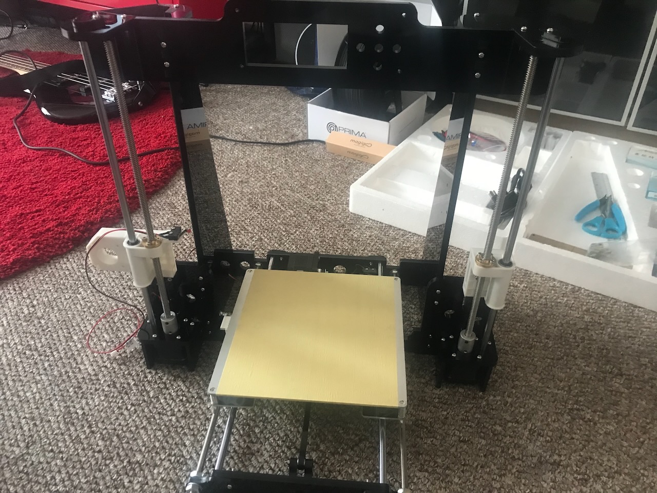
The two 345mm 8mm lead screws are then threaded through the nut supports and fixed to the Z motors.
Important
There needs to be a slight gap between the lead screws and the motor shafts to allow a little bit of flex in the couplers.
Parts Used
| Item | Quantity |
|---|---|
| Step 13 | 1 |
| T type lead screw 345mm | 2 |
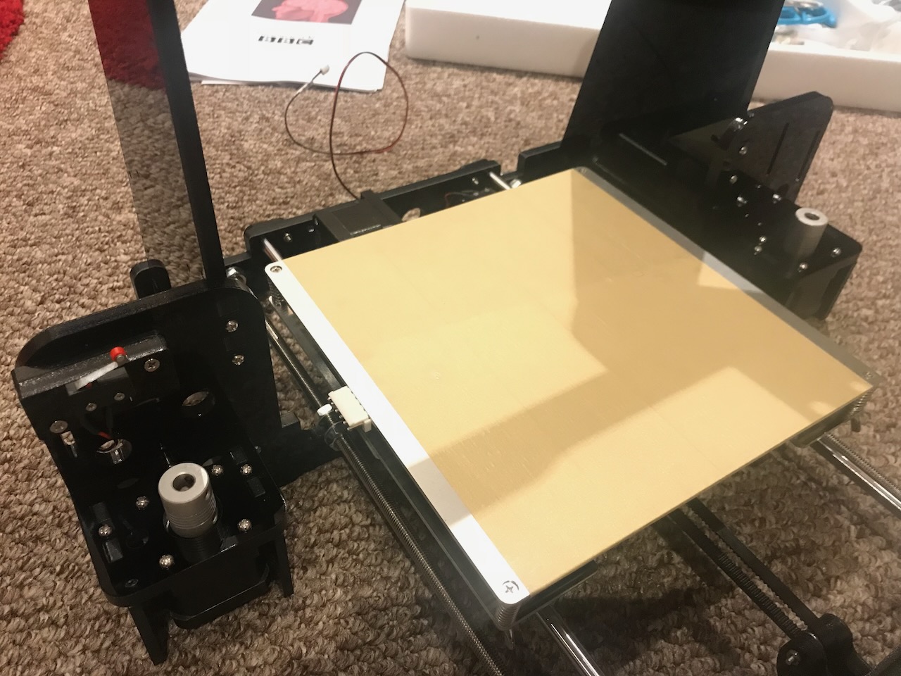
X Axis
✅ Assembly Step 16
3 linear bearing blocks are added to the two 436mm guide rods, 2 on the top rod 1 on the bottom and then press fitted into the nut supports.
Parts Used
| Item | Quantity |
|---|---|
| Step 14 | 1 |
| X axis guide rod | 2 |
| Linear bearing | 3 |
✅ Assembly Step 17 & 18
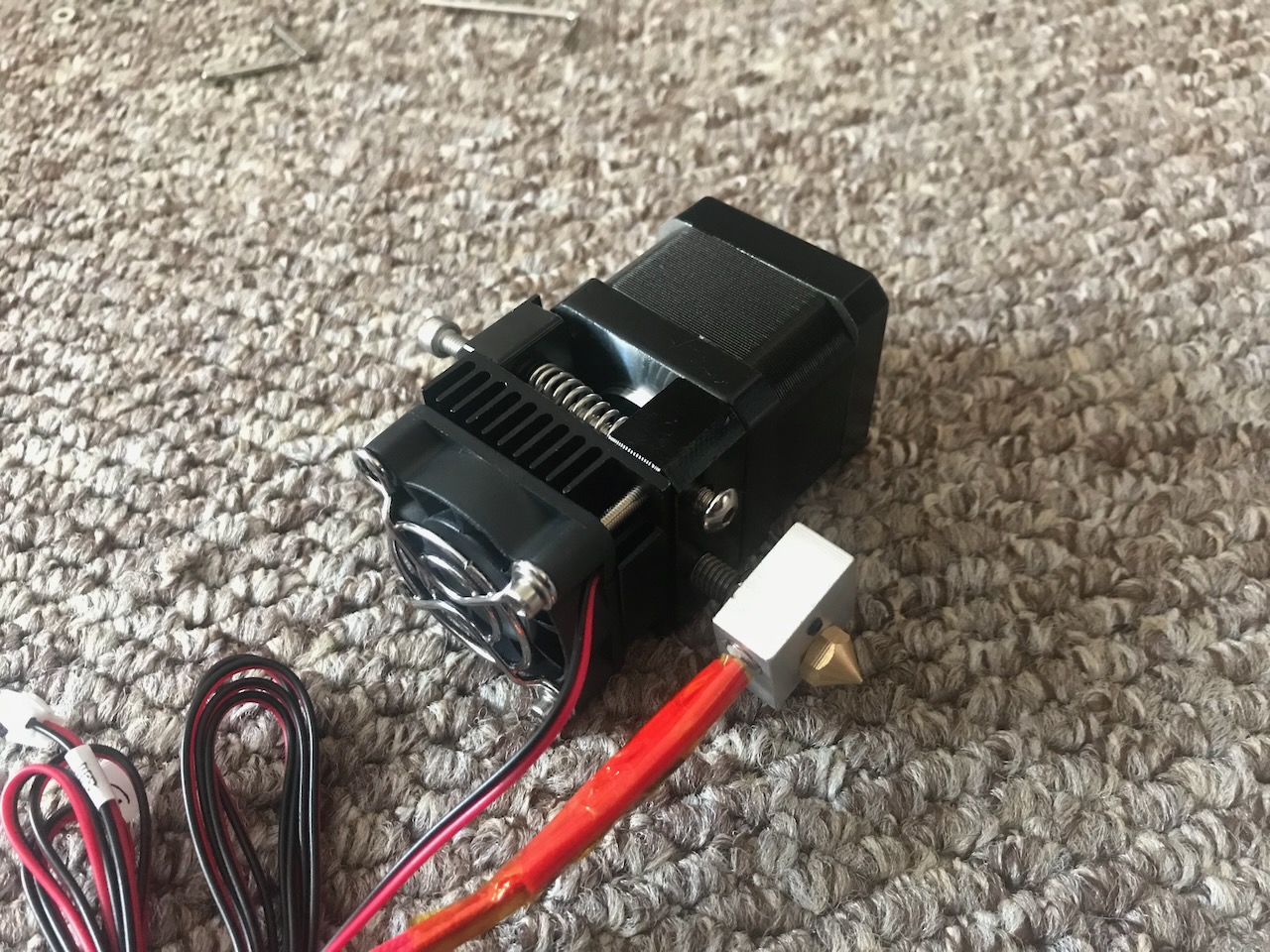
The M4x6 screw is removed from the bottom of the extruder assembly, The extruder is removed from it's carrier, the M3x20 screws removed from the bottom of the extruder motor and the fan and heatsink are installed.
Parts Used
| Item | Quantity |
|---|---|
| Extruder | 1 |
| 40x40x10 Axial Fan (12V) | 1 |
| 40x40x10 Heatsink | 1 |
| Fan cover | 1 |
| M3x45 Screw | 2 |
| M3 Spacer | 6-8 |
✅ Assembly Step 19
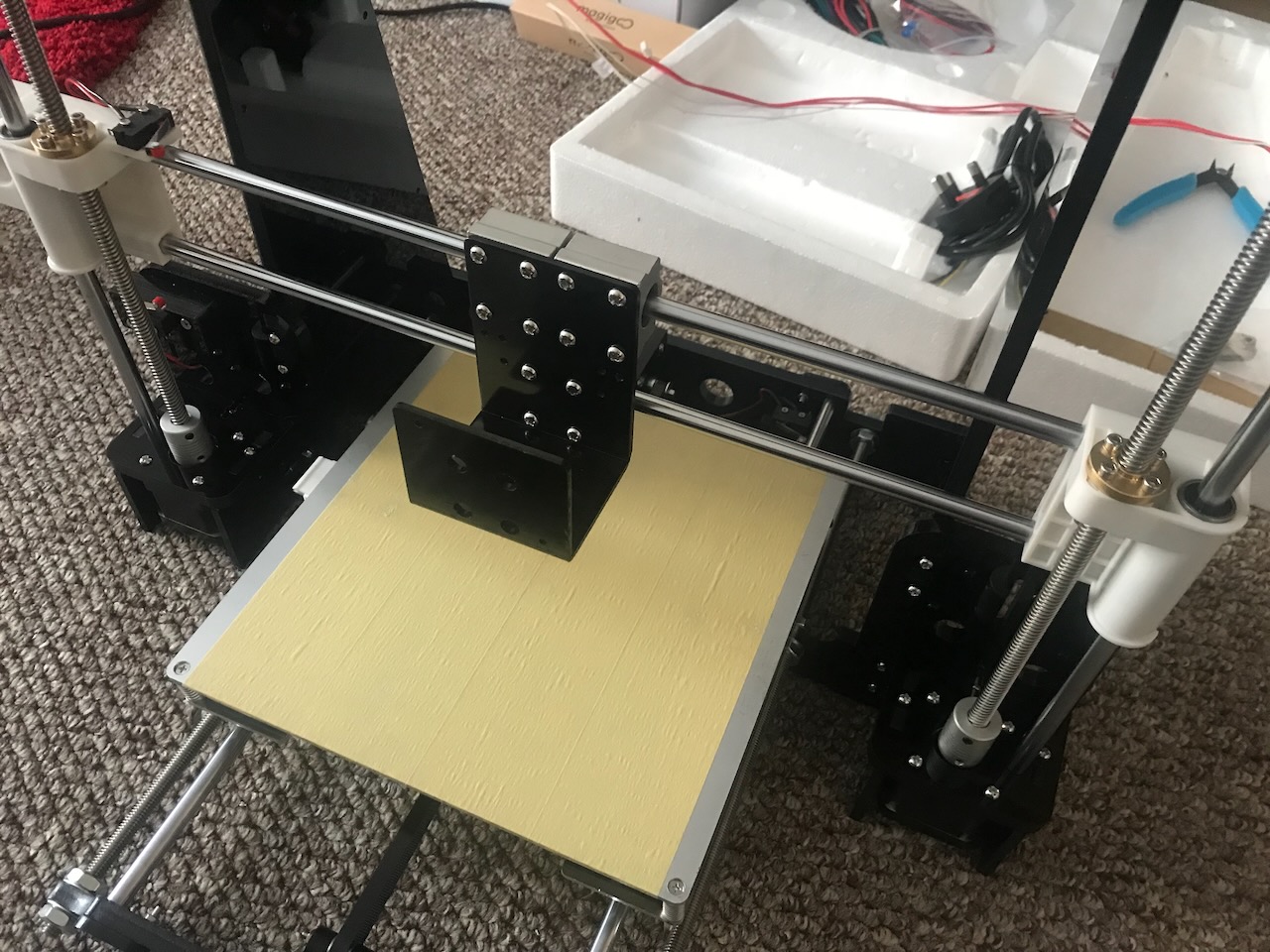
The X axis carriage is then attached to the X axis linear bearing blocks.
Parts Used
✅ Assembly Step 20
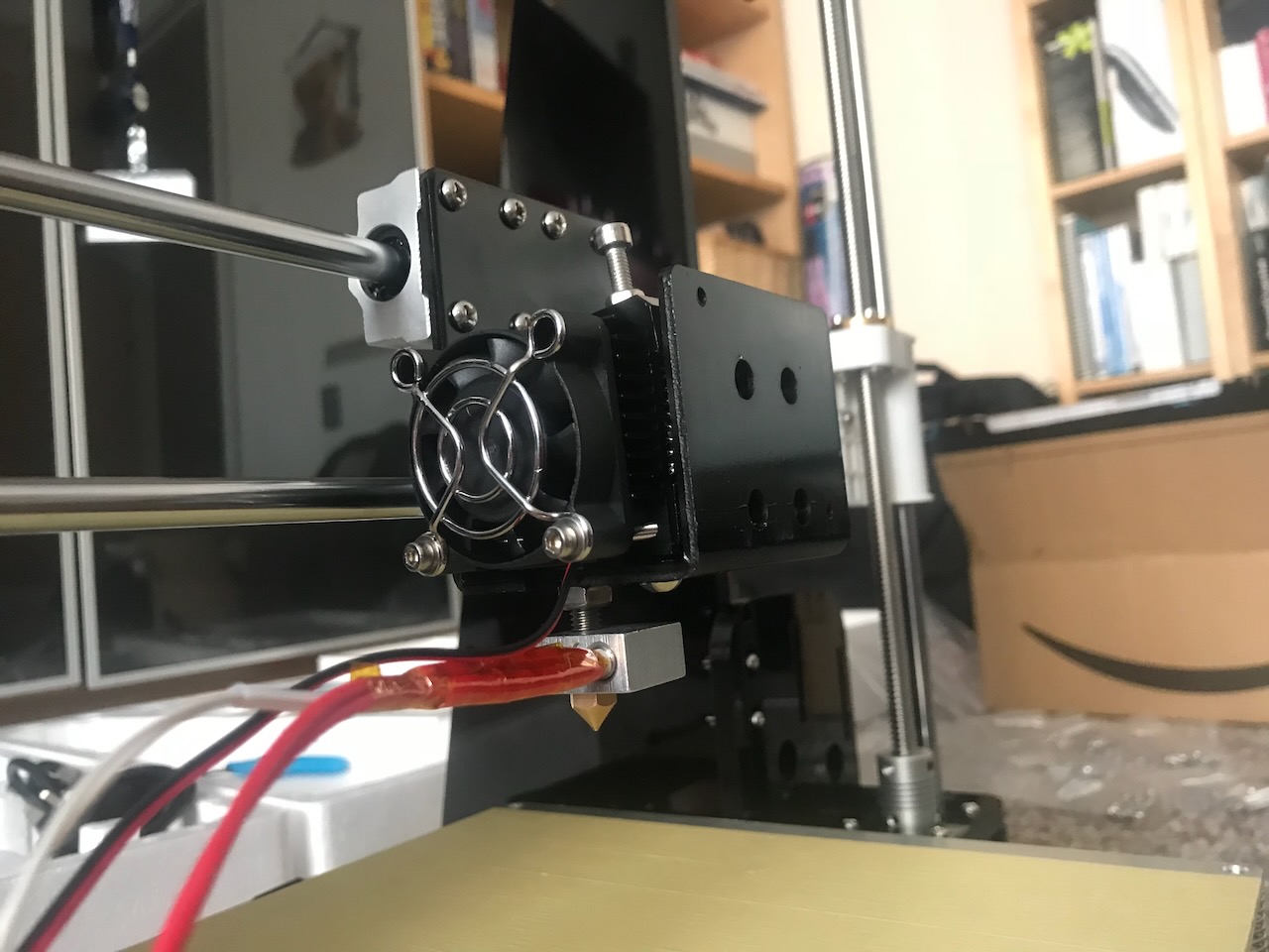
And the extruder is attached to the carriage.
Parts Used
✅ Assembly Step 21
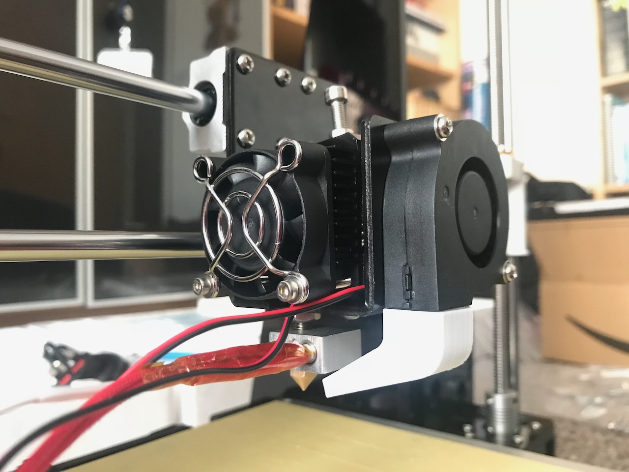
The part cooling fan is fixed to the front of the carriage.
Parts Used
| Item | Quantity |
|---|---|
| Step 20 | 1 |
| 50x50x15 Centrifugal Fan (12V) | 1 |
| Printed fan duct | 1 |
| M3x18 Screw | 2 |
✅ Assembly Step 22
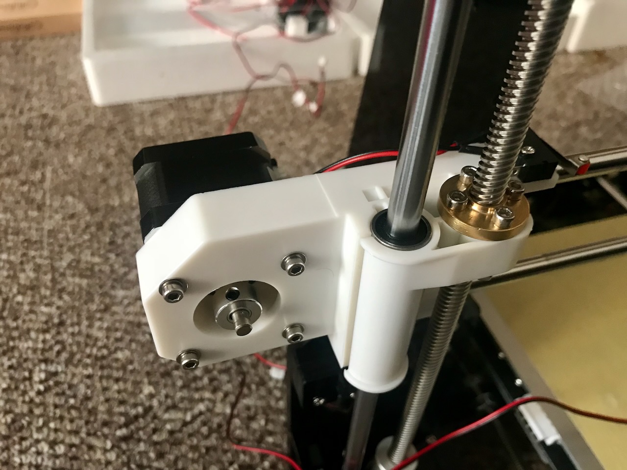
The X axis motor is attached to the left Z axis nut support.
Tip
I added M3 Spacers here as the heads of the screws are quite small and were biting too much into the plastic.
Parts Used
| Item | Quantity |
|---|---|
| X shaft motor | 1 |
| Left Z shaft nut support | 1 |
| M3x20 Screw | 4 |
| M3 Spacer | 4 |
✅ Assembly Step 23 & 24
The X axis belt is then installed and the carriage is moved back and forth along the rails to ensure the travel is smooth.
Warning
The extruder has to be removed temporarily to fit the nuts for the belt clamps. These should really have been added in to the extruder carrier in Step 19.
Parts Used
| Item | Quantity |
|---|---|
| Belt | 1 |
| M3x18 Screw | 2 |
| M3 Nut | 4 |
| Cable ties | 4 |
Electronics
✅ Assembly Step 25
the LCD 2004 screen is installed into the frame sandwiched between the top support plate and the screen baffle plate.
Parts Used
| Item | Quantity |
|---|---|
| LCD 2004 screen | 1 |
| Pillar washer M3x7 | 4 |
| Screen baffle plate | 1 |
| M3x30 Screw | 4 |
| M3 Nut | 8 |
✅ Assembly Step 26 & 27
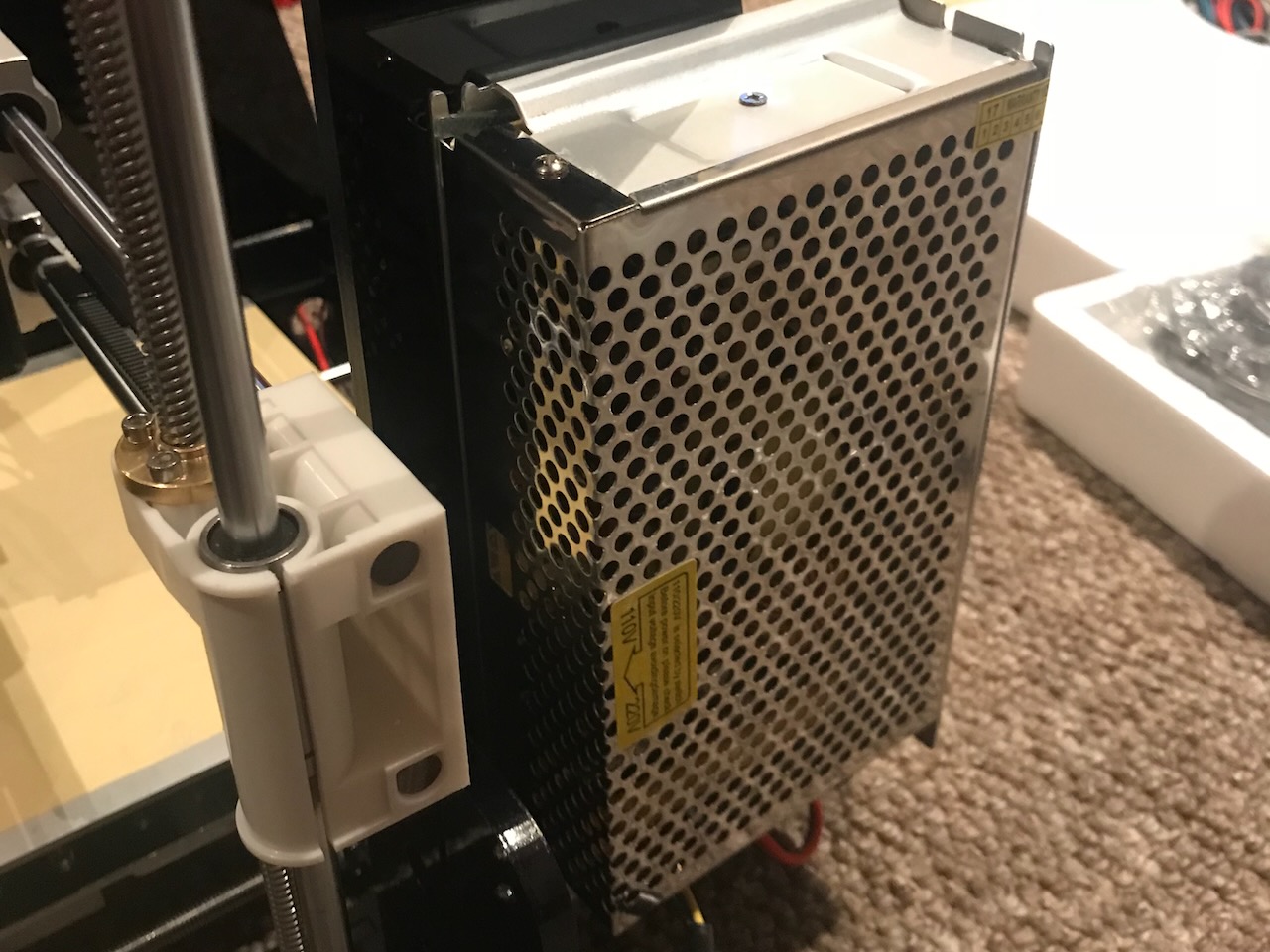
The 12V power supply is fixed into place on the right of the frame.
Parts Used
| Item | Quantity |
|---|---|
| Step 25 | 1 |
| Power Supply 12V | 1 |
| M3x12 Screw | 3 |
✅ Assembly Step 28
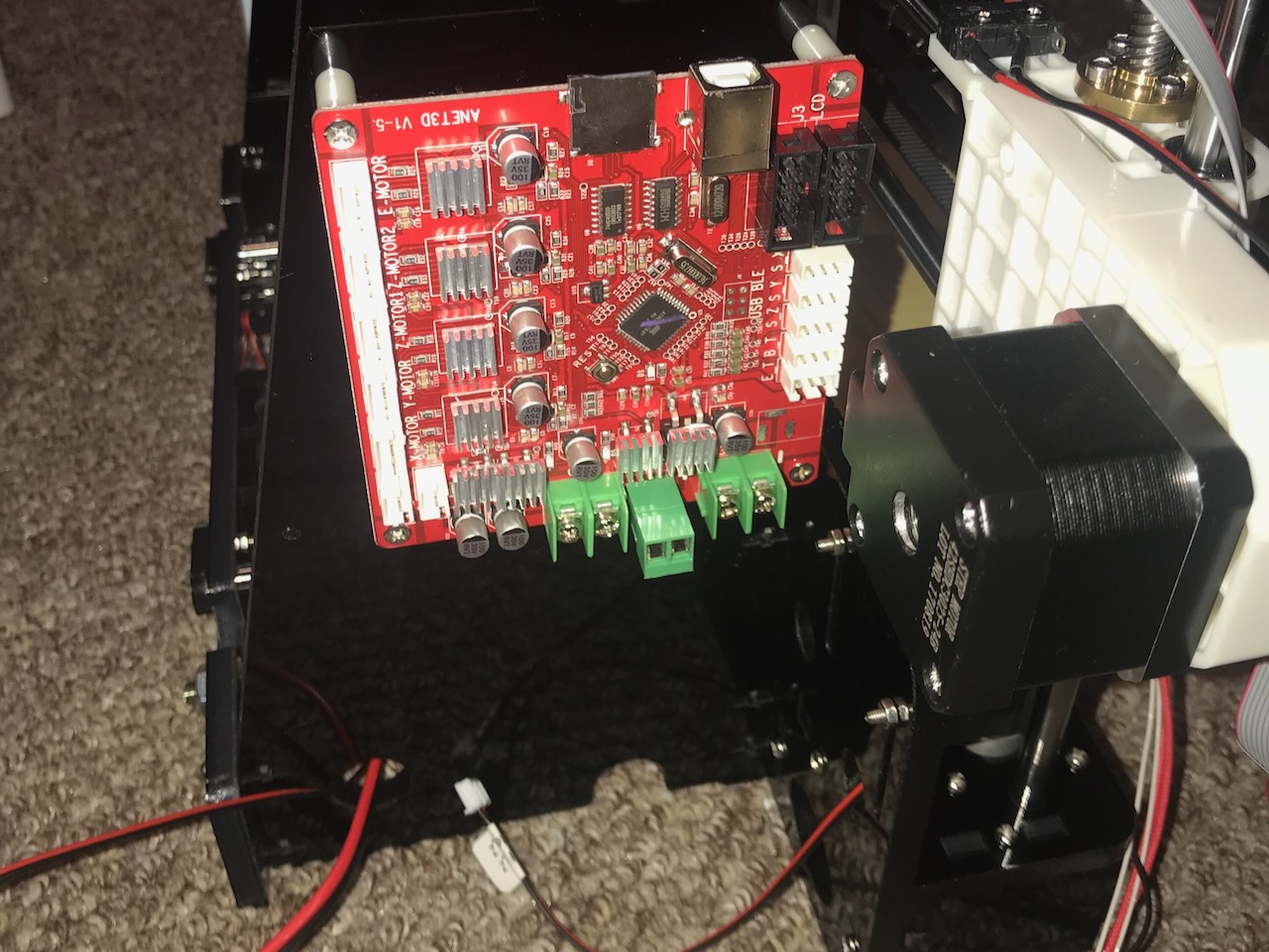
The control board is fixed into place on the left side of the frame.
Parts Used
| Item | Quantity |
|---|---|
| Step 25 | 1 |
| Mainboard | 1 |
| M3x12 Screw | 4 |
| M3 Nut | 4 |
| Pillar washer M3x15 | 4 |
✅ Assembly Step 29 & 30
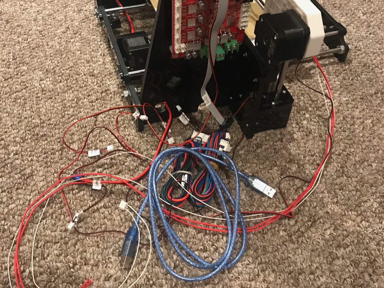
The various wires are then plugged into the correct spots on the power supply and control board.
Parts Used
| Item | Quantity |
|---|---|
| Power supply wire | 700mm |
| X motor wire | 400mm |
| Y motor wire | 400mm |
| Left Z motor wire | 400mm |
| Right Z motor wire | 900mm |
| X limit switch wire | 550mm |
| Y limit switch wire | 700mm |
| Z limit switch wire | 200mm |
| Extruder motor wire | 900mm |
| 4010 Fan wire | 1100mm |
| 5015 Blower wire | 1100mm |
| Heating pipe wire | 1000mm |
| Extruder thermistor wire | 1000mm |
| Hotbed wire | 900mm |
| Screen wire | 500mm |
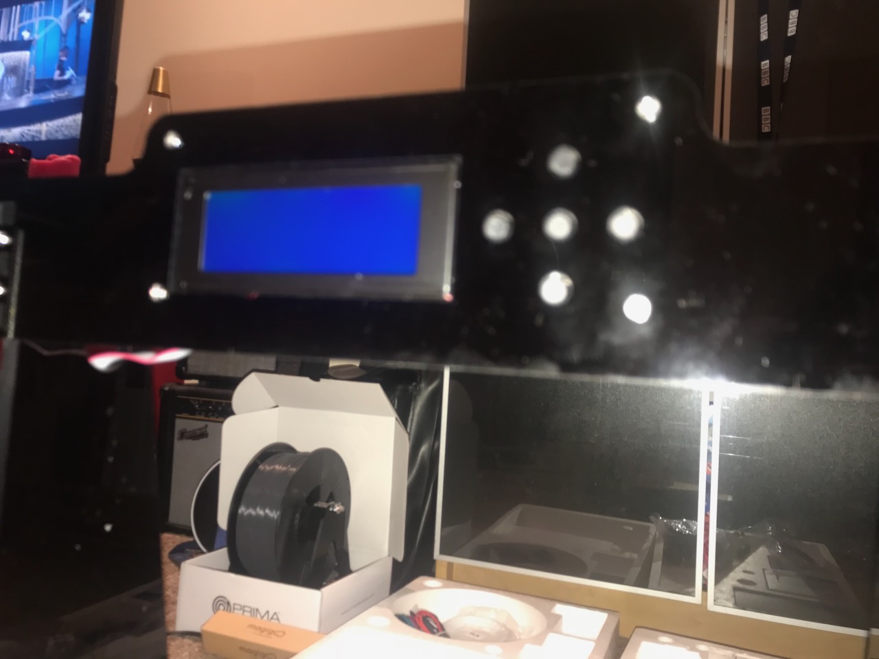
Testing
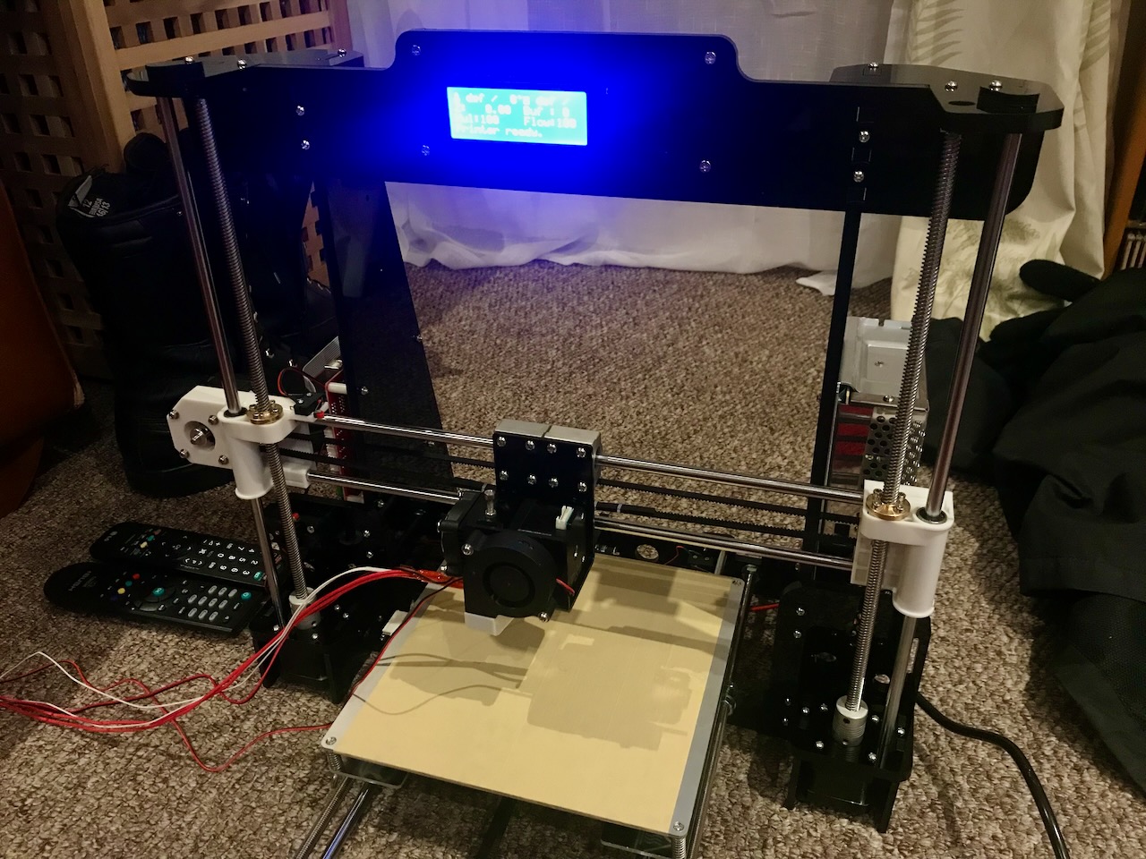
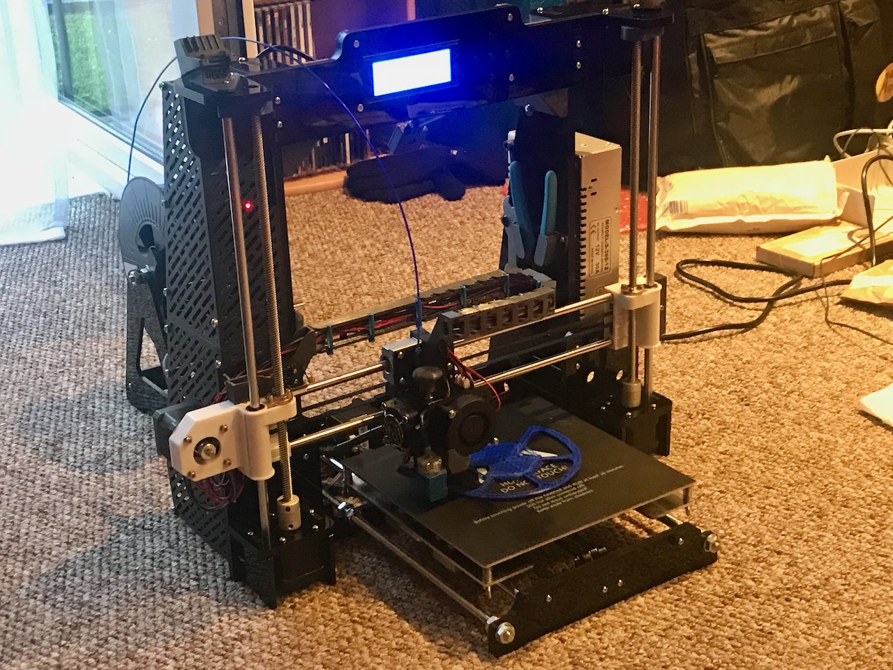
After double checking the wires are plugged into place in the correct polarity the printer is turned on for the first time.
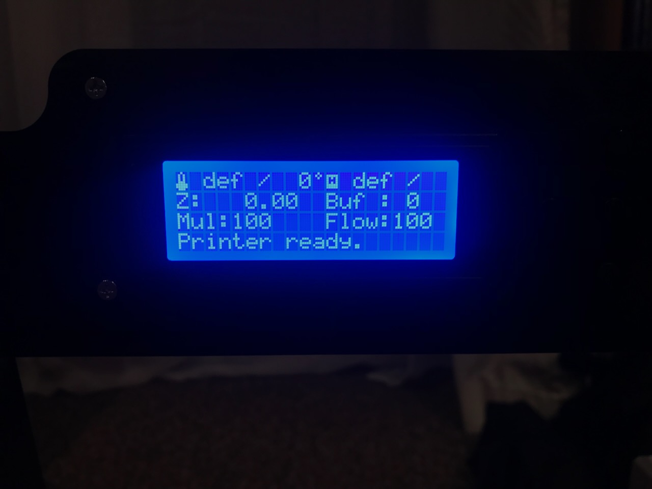
Always good to see that something is displayed on the screen.
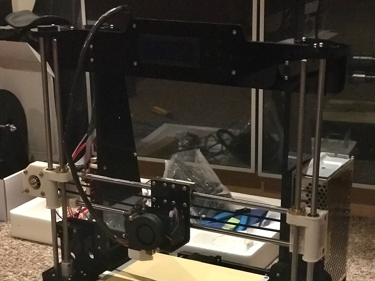
The wires are then tidied up with the included spiral wrap to keep them getting snagged on any moving parts.
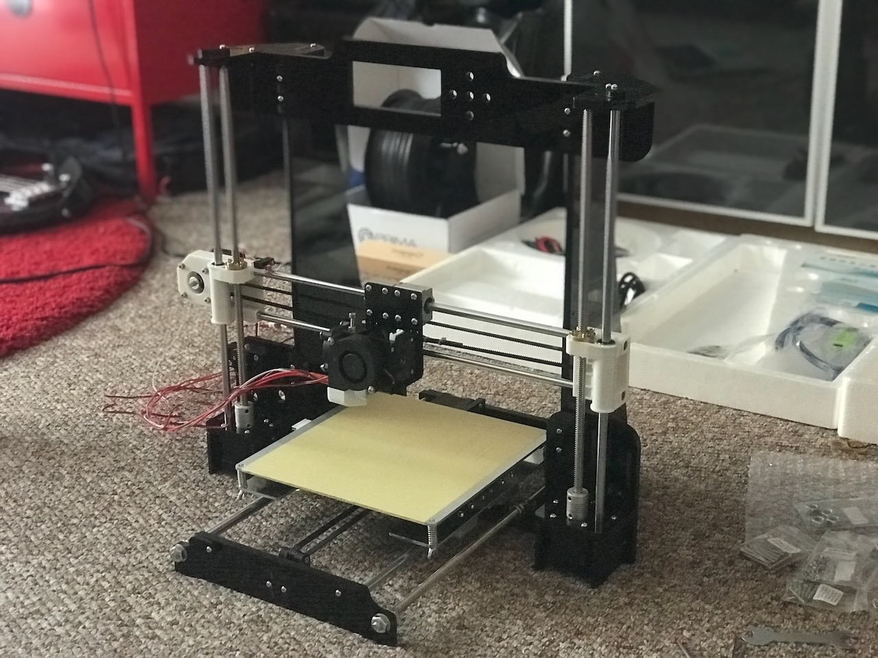
Finished
The hello world of the 3D printing world... the first print had to be a 3D Benchy.
Safety Upgrades
The Anet A8 has a bit of a reputation for catching on fire and burning your house down these upgrades are a must to ensure safety of using the printer.
- 30A power supply
- Stand alone Mosfets for the Heated Bed and Hotend
- Flash Marlin 2 to enable thermal runaway protection
I also ran 2 more cables to the bed to spread the current load between the extra pins on the heated bed because the movement of the bed can make the pins loose which in turn can make them melt the connector due to the high current.
Firmware
The full configured firmware to run the printer with the auto bed level sensor is available on my Marlin Github repository.
In Marlin/Configuration.h Update:
#define STRING_CONFIG_H_AUTHOR "(Mike Thomas, Anet config)"
#define BAUDRATE 115200
#define MOTHERBOARD BOARD_ANET_10
#define CUSTOM_MACHINE_NAME "Anet A8"
Temperature Sensors
#define TEMP_SENSOR_0 11
#define TEMP_SENSOR_BED 5
#define TEMP_RESIDENCY_TIME 6
#define TEMP_BED_RESIDENCY_TIME 6
#define BED_MAXTEMP 130
PID Tuning
The easiest way I have found to find the values to use for PID Tune is to use the PID_AUTOTUNE_MENU:
#define PID_AUTOTUNE_MENU
Once you have flashed with it enabled you can run an autotune from the Advanced Settings menu.
You can then add the values to the config:
#define DEFAULT_Kp 19.3532
#define DEFAULT_Ki  1.1057
#define DEFAULT_Kd 84.6825
For the bed you will have to enable:
#define PIDTEMPBED
...and update the values in the config:
#define DEFAULT_bedKp 236.5893
#define DEFAULT_bedKi  45.2326
#define DEFAULT_bedKd 824.9868
Endstops
The Anet A8 comes with endstops that are wired Normally Open (NO) therefore the endstop logic needs to be inverted.
#define X_MIN_ENDSTOP_INVERTING true
#define Y_MIN_ENDSTOP_INVERTING true
#define Z_MIN_ENDSTOP_INVERTING true
The endstop pins on the Anet A8 mainboard are interrupt-capable so to save CPU cycles it's good to enable:
#define ENDSTOP_INTERRUPTS_FEATURE
Speeds and Feeds
I started with the values from the Anet A9 sample config and have slightly tuned them to fit my needs.
#define DEFAULT_AXIS_STEPS_PER_UNIT { 100, 100, 400, 105.35 }
#define DEFAULT_MAX_FEEDRATE { 400, 400, 8, 50 }
#define DEFAULT_MAX_ACCELERATION { 2000, 2000, 100, 10000 }
#define DEFAULT_ACCELERATION          500
#define DEFAULT_RETRACT_ACCELERATION  1000
#define DEFAULT_TRAVEL_ACCELERATION   1000
Auto Bed Levelling
To enable auto bed levelling on the printer I used a Tronxy XY-08N.
#define Z_MIN_PROBE_ENDSTOP_INVERTING true
#define FIX_MOUNTED_PROBE
#define NOZZLE_TO_PROBE_OFFSET { -25, -45, 0 }
#define PROBING_MARGIN 50
#define XY_PROBE_FEEDRATE (100*60)
#define AUTO_BED_LEVELING_BILINEAR
#define Z_SAFE_HOMING
#define HOMING_FEEDRATE_MM_M { (100*60), (100*60), (4*60) }
Machine
The steppers moved the wrong way when homing the printer for the first time therefore I had to invert the axes from defaults:
#define INVERT_Y_DIR false
#define INVERT_Z_DIR true
#define X_BED_SIZE 220
#define Y_BED_SIZE 220
#define X_MIN_POS -33
#define Y_MIN_POS -10
#define Z_MAX_POS 240
#define SOFT_ENDSTOPS_MENU_ITEM
#define EEPROM_SETTINGS
#define SDSUPPORT
Display
#define ANET_FULL_GRAPHICS_LCD