Building my first Voron printer

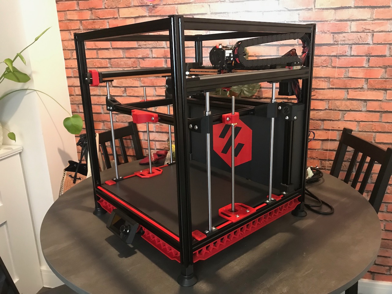
Table of contents
Sourcing Parts
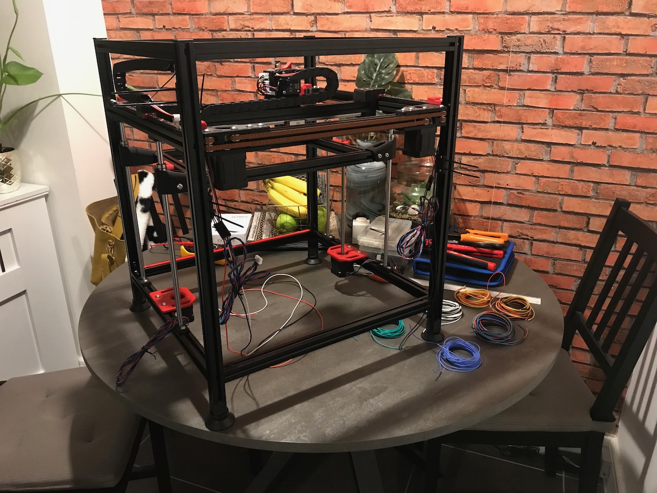
I had originally chosen parts for the Hypercube that will lead up to re-building it into a Voron 1.8. However, I have chosen to build a new printer rather than upgrade my existing one in case I need to reprint more parts. I have already sourced many of the parts on the BOM from the configurator and I will replace some with alternatives that I already have (see the notes columns for details).
The quantities here are from the 1.8 BOM, however I am planning on swapping out a few parts for the updated versions from the Trident. Therefore these quantities may not be accurate and I will also need to source more items for some Mods and future upgrades that I would like to implement.
Fasteners
| Item | Quantity | Received | Notes |
|---|---|---|---|
| M5x40 SHCS | 8 | 29 | |
| M5x30 BHCS | 6 | 15 | |
| M5x16 BHCS | 67 | 69 | |
| M5x10 BHCS | 71 | 104 | |
| M5 Hexnut | 8 | 19 | |
| M5 1mm Spacer | 20 | 50 | |
| M5 T-nut | 83 | 130 | |
| M4x6 BHCS | 4 | 20 | |
| M3x40 SHCS | 5 | 20 | |
| M3x30 SHCS | 25 | 30 | |
| M3x20 SHCS | 10 | 26 | |
| M3x16 SHCS | 17 | 66 | |
| M3x12 SHCS | 30 | 77 | |
| M3x8 SHCS | 171 | 254 | |
| M3x6 BHCS | 20 | 47 | |
| M3 Hexnut | 7 | 50 | |
| M3 Washer | 10 | 50 | |
| M3 T-nut | 120 | 160 | |
| M3 Hammer Head T-nuts | 54 | 97 | |
| M3 Threaded Insert | 50 | 78 | |
| M3 Knurled Nut (DIN 466-B) | 1 | 5 | BOM specifies 3, replacing 2 rear with M4s |
| M4 Knurled Nut (DIN 466-B) | 2 | 5 | Using these instead of 2 M3 at rear of bed |
| M2x10 Self-Tapping Screw | 7 | 51 | |
| Yellow Die Spring - M3 | 1 | 10 |
Vibration Management
| Item | Quantity | Received | Notes |
|---|---|---|---|
| Rubber Compressor Foot | 4 | 4 |
Frame
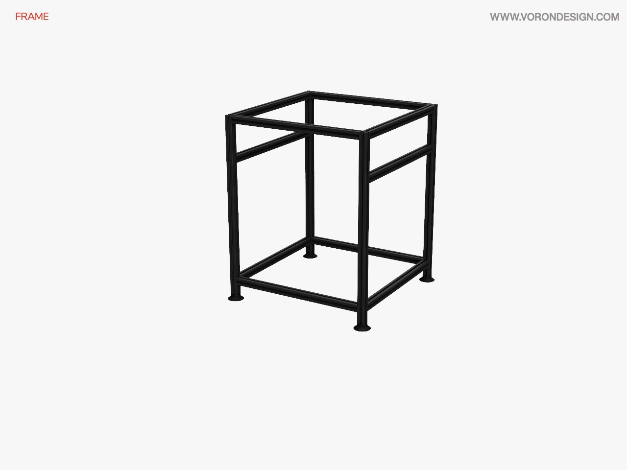
Image © 2020 Voron Design
| Item | Quantity | Received | Notes |
|---|---|---|---|
| DIN 3 Rails (35mm W) - 420mm | 3 | 3 | BOM only specifies 2 but manual has 3 |
| Misumi HFSB5-2020-290 | 1 | 1 | In LDO V1.8 300 Frame Kit |
| Misumi HFSB5-2020-420-TPW | 10 | 10 | In LDO V1.8 300 Frame Kit |
| Misumi HFSB5-2020-420 | 1 | 1 | In LDO V1.8 300 Frame Kit |
| Misumi HFSB5-2020-230 | 2 | 2 | In LDO V1.8 300 Frame Kit |
| Misumi HFSB5-2020-380 | 1 | 1 | In LDO V1.8 300 Frame Kit |
| Misumi HFSB5-2020-500-LTP-RCP-AV380-AP40 | 4 | 4 | In LDO V1.8 300 Frame Kit |
| Misumi HFSB5-2020-200-TPW | 2 | 2 | In LDO V1.8 300 Frame Kit |
| Misumi HFSB5-2020-420-AH45-BH375 | 2 | 2 | In LDO V1.8 300 Frame Kit |
I have looked into a few different options for a new frame for my 3D Printer and eventually settled on an LDO frame kit for a Voron 1.8. All these parts (Except for the DIN rails) come from this kit.
Motion
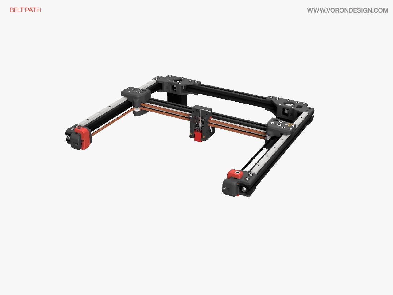
Image © 2020 Voron Design
| Item | Quantity | Received | Notes |
|---|---|---|---|
| GT2 20T Pulley (5mm ID 6mm W) | 3 | 3 | |
| GT2 20T Toothed Idler (5mm ID 6mm W) | 2 | 4 | |
| F695 Bearing | 20 | 30 | |
| LM8LUU Linear Bearing | 4 | 4 | |
| TR8x4 Leadscrew Nut | 2 | 2 | Replaced the stock LDO Brass ones with Delrin |
| 5x30mm Shaft | 1 | 1 | |
| BMG Extruder Components Kit | 1 | 1 | |
| Linear Rail MGN9H 350mm | 4 | 4 | |
| Linear Shaft 8x320mm | 4 | 4 | |
| GT2 Open Belt LL-2GT-6 (6mm wide) - 1890mm | 2 | 4 |
Print Bed
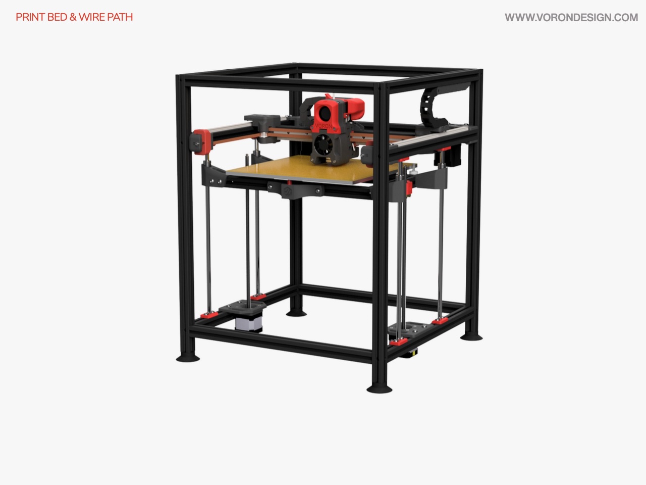
Image © 2020 Voron Design
| Item | Quantity | Received | Notes |
|---|---|---|---|
| 3M 468MP Adhesive Sheet - 12"x12" | 1 | 1 | Came with Energetic 300x300mm PEI Spring Steel Sheet + Magnet |
| PEI 0.04" Sheet - 12"x12" | 1 | 1 | Came with Energetic 300x300mm PEI Spring Steel Sheet + Magnet |
| MIC6 5/16" Plate - 12"x12" | 1 | 1 | Anodised Black |
| Keenovo Silicone AC Heater w/ thermistor - 250x250mm (450W) | 1 | 1 | Keenovo 240V 600W 240x240mm |
Wires
| Item | Quantity | Received | Notes |
|---|---|---|---|
| Nylon Cable Ties 4" | 40 | 100 | |
| 1/2" Braided Cable Sheathing (ft) | 5 | 16 | |
| 20AWG Silicone Cable (ft) | 10 | 137 | in various colours |
| 24AWG Silicone Cable (ft) | 100 | 177 | in various colours |
| Spade Crimp Terminal 4.8mm Female | 10 | 20 | |
| JST XH Connector Plug 4 Position | 5 | 20 | |
| JST XH Connector Plug 3 Position | 4 | 20 | |
| JST XH Connector Plug 2 Position | 2 | 20 | |
| JST XH Female Pin | 40 | 200 | |
| MicroFit3 Connector Plug 4 Position | 2 | 10 | |
| MicroFit3 Connector Plug 3 Position | 1 | 10 | |
| MicroFit3 Connector Plug 2 Position | 5 | 10 | |
| MicroFit3 Connector Receptacle 4 Position | 2 | 10 | |
| MicroFit3 Connector Receptacle 3 Position | 1 | 10 | |
| MicroFit3 Connector Receptacle 2 Position | 5 | 10 | |
| MicroFit3 Female Pin | 40 | 140 | |
| MicroFit3 Male Pin | 40 | 140 | |
| 10x11 Cable Chain - 1m | 2 | 2 |
Electronics
| Item | Quantity | Received | Notes |
|---|---|---|---|
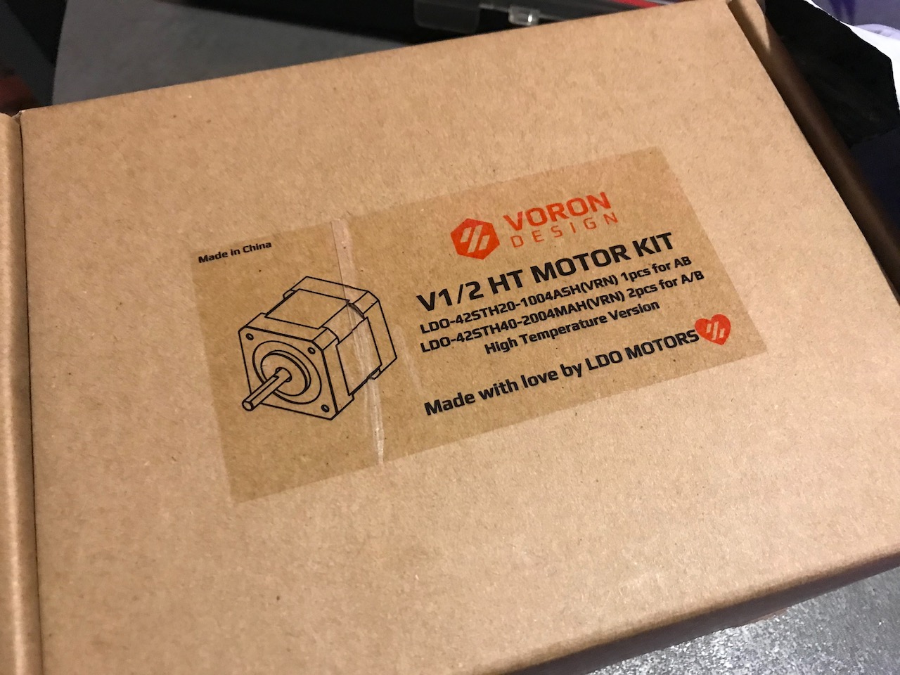
| NEMA17 Motor 17HS19-2004S | 2 | 2 | Ordered some larger ones than that are in the LDO Voron V1/V2 HT Motor Kit |
| SPDT KW10 Limit Micro Switch | 3 | 30 | |
| PL-08N Inductive Probe | 1 | 1 | Purchased an Omron TL-Q5MC2. Going to replace with Klicky Probe |
| E3D V6 Bowden Hotend Kit (24V) | 1 | 1 | |
| 40x40x20 Centrifugal Fan (24V) | 1 | 1 | GDSTime Fan |
| 40x40x10 Axial Fan (24V) | 1 | 1 | GDSTime Fan |
| Mini 12864 Display | 1 | 1 | |
| Inlet Power Socket IEC320 C14 | 1 | 1 | |
| Keystone CAT6 Insert (Optional) | 1 | 2 | 1 Ethernet and 1 USB |
| 60x60x20 Fan (24V) | 2 | 2 | GDSTime Fans |
| BigTreeTech SKR 1.4 | 1 | 1 | I have the Turbo version |
| TMC2209 Stepper Motor Driver | 5 | 5 | |
| USB Cable A-male B-male | 1 | 1 | |
| Raspberry Pi 4 | 1 | 1 | 4GB RAM Version |
| Mean Well LRS-200-24 PSU | 1 | 1 | |
| Mean Well RS-25-5 PSU | 1 | 1 | |
| Omron G3A-210B-DC5 SSR | 1 | 1 | |
| DIN Rail Mount Bracket for G3A SSR | 1 | 1 | |
| BAT85 Diode | 1 | 7 | I have purched the ERCF toolhead board which has the BAT85 Diode integrated. |
| C13 Power Cord | 1 | 3 | |
| Thermal Fuse (120C) | 1 | 5 | |
| NEMA17 Motor 17HS08-1004S | 1 | 1 | In LDO Voron V1/V2 HT Motor Kit |
| NEMA17 TR8x4 300mm Linear Stepper | 2 | 2 | In LDO V1 Z Motor Kit |
| BigTreeTech Smart Filament Sensor V2 | 2 | 2 |
Panels
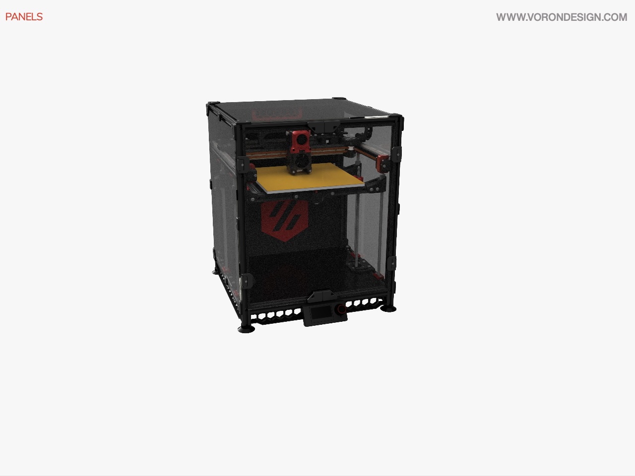
Image © 2020 Voron Design
| Item | Quantity | Received | Notes |
|---|---|---|---|
| Coroplast Sheet - 420x420x4 mm | 1 | 1 | Brought 5 A1 3mm sheets to cut to size and 1mm foam tape to avoid vibrations |
| Coroplast Sheet - 435x435x4 mm | 1 | 1 | Brought 5 A1 3mm sheets to cut to size and 1mm foam tape to avoid vibrations |
| Coroplast Sheet - 198x434x4 mm | 1 | 1 | Brought 5 A1 3mm sheets to cut to size and 1mm foam tape to avoid vibrations |
| Coroplast Sheet - 246x434x4 mm | 1 | 1 | Brought 5 A1 3mm sheets to cut to size and 1mm foam tape to avoid vibrations |
| Coroplast Sheet - 236x415x4 mm | 1 | 1 | Brought 5 A1 3mm sheets to cut to size and 1mm foam tape to avoid vibrations |
| Coroplast Sheet - 242x46x4 mm | 2 | 2 | Brought 5 A1 3mm sheets to cut to size and 1mm foam tape to avoid vibrations |
| Coroplast Sheet - 419x66x4 mm | 1 | 1 | Brought 5 A1 3mm sheets to cut to size and 1mm foam tape to avoid vibrations |
| Acrylic Sheet Clear - 217x444x2.5 mm | 2 | 2 | 3mm thickness |
| Acrylic Sheet Clear - 434x444x2.5 mm | 2 | 2 | 3mm thickness |
| Acrylic Sheet Clear - 434x434x2.5 mm | 1 | 1 | 3mm thickness |
Misc
| Item | Quantity | Received | Notes |
|---|---|---|---|
| Fume Extractor Carbon Filter Element | 1 | 1 | |
| 4mm Bowden Coupler | 1 | 4 | |
| Bowden Tube (m) | 1 | 3 | |
| 3M VHB Tape 5952 | 1 | 1 | |
| Loctite Blue Threadlocker Stick | 1 | 1 | |
| Mobil EP2 Grease | 1 | 1 | |
| Tesa Wire Loom Harness Tape | 1 | 1 | |
| 1mm Foam Tape | 1 | 1 | |
| 6x3mm Neodimium Magnet | 8 | 41 | |
| PTFE Tube (4mm OD 3mm ID) - 1m | 1 | 1 |
Assembling The Frame
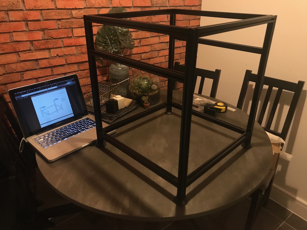
Parts Used
| Item | Quantity |
|---|---|
| M5x16 BHCS | 20 |
| M5x30 BHCS | 4 |
| Misumi HFSB5-2020-420-TPW | 10 |
| Misumi HFSB5-2020-500-LTP-RCP-AV380-AP40 | 4 |
| Rubber Compressor Foot | 4 |
Printing Parts
All printed parts will be printed in eSun ABS+. The Voron team recommends an infill type of 40% of either Grid, Gyroid, Honeycomb, Triangle or Cubic. A layer height of 0.2mm and extrusion width of 0.4mm, with a wall count of 4 and top/bottom layers of 5.
Tools
| Item | Quantity | Material | Printed | Notes |
|---|---|---|---|---|
| rail_installation_guide_center | 2 | eSun ABS+ (Black) | ✔️ | |
| v1.8_extrusion_drilling_jig | 1 | ❌ | Not Required as I brought my frame as a kit | |
| pulley_jig | 1 | eSun ABS+ (Black) | ✔️ | This is a 2.4 Part, has spacer for extruder gear |
| TensionMeter | 1 | eSun ABS+ (Black) | ✔️ | This is a Voron Users Mod by Kruppes |
| lower_extrusion_alignment | 1 | Tinmorry PETG (Black) | ✔️ | This is a Voron Users Mod by natewalck |
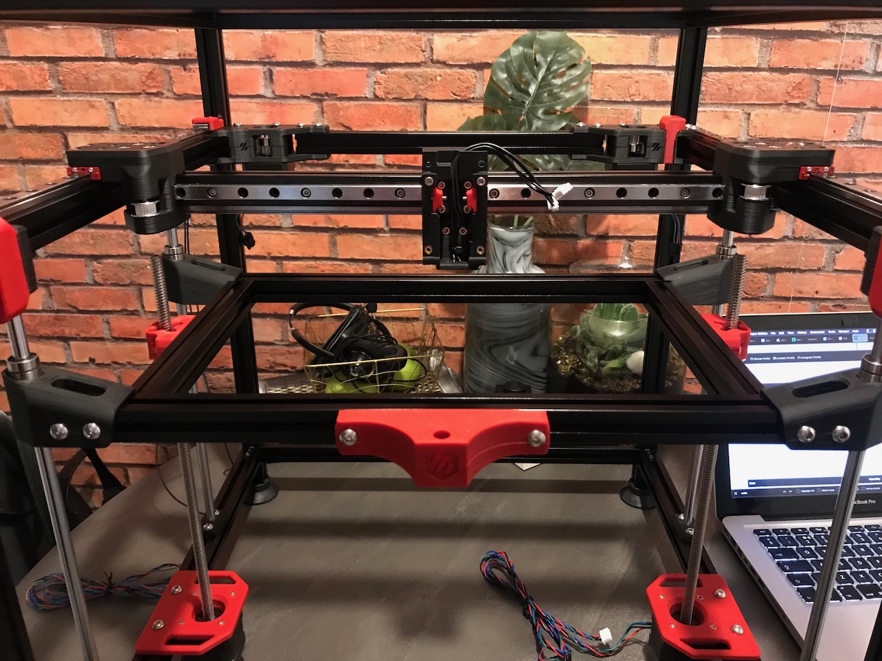
Gantry
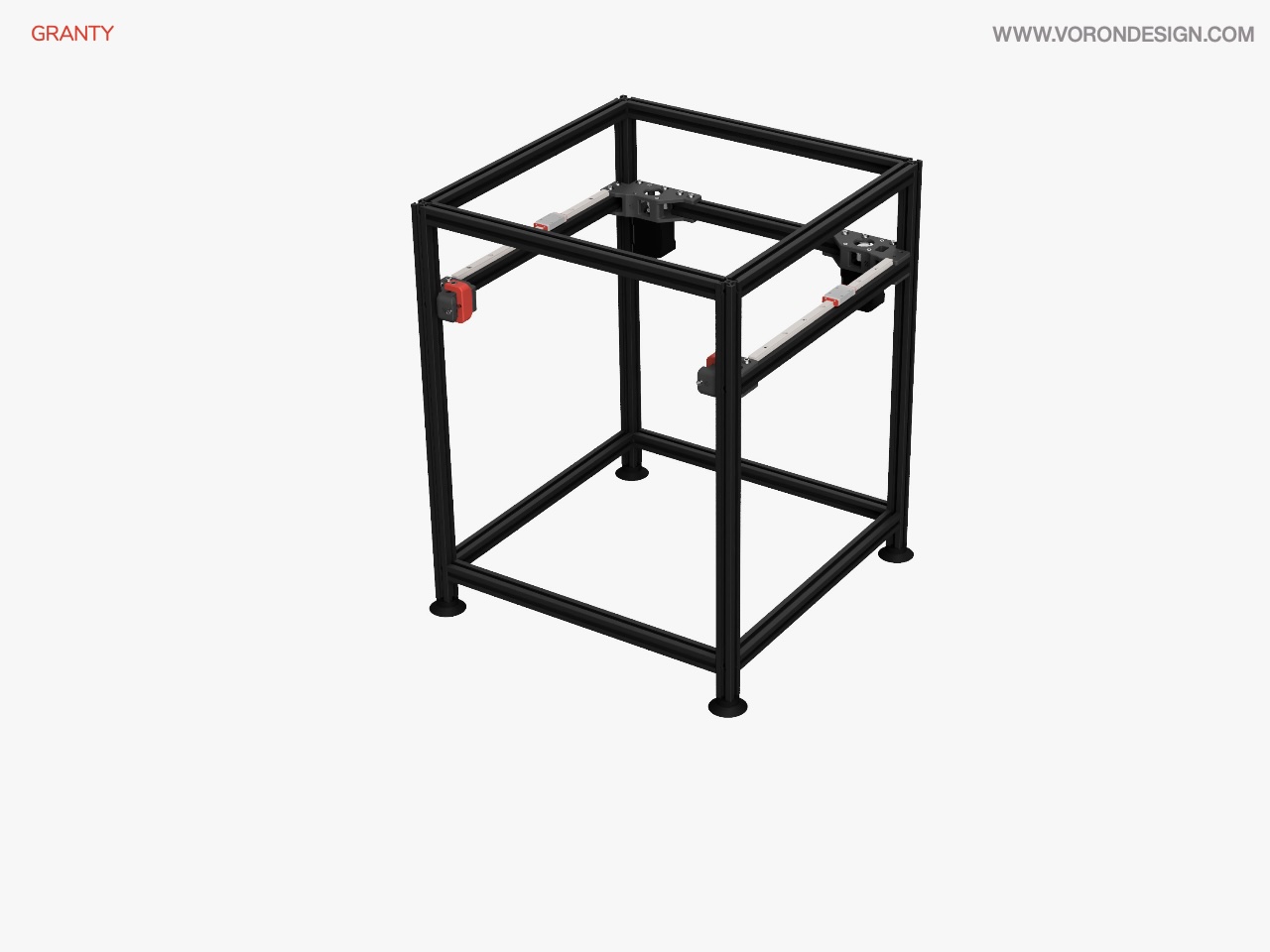
Image © 2020 Voron Design
Some of the gantry parts (specifically the AB Drive Units and Front Idlers) will be replaced with the upgraded versions from the Trident as they should fit the 1.8.
✅ AB Drive Units
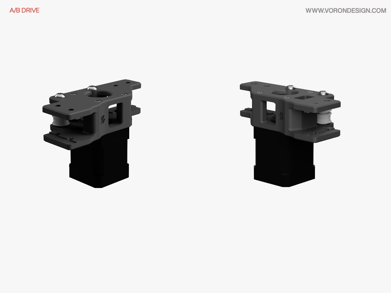
Image © 2020 Voron Design
| Item | Quantity | Material | Size | Weight | Cost | Printed | Notes |
|---|---|---|---|---|---|---|---|
| wire_cover | 1 | eSun ABS+ (Fire Engine Red) | 1.30m | 3.31g | £0.06 | ✔️ | This is a Trident Part |
| a_drive_frame_lower | 1 | eSun ABS+ (Black) | 8.58m | 21.86g | £0.42 | ✔️ | This is a Trident Part |
| a_drive_frame_upper | 1 | eSun ABS+ (Black) | 8.21m | 20.93g | £0.40 | ✔️ | This is a Trident r1 Part |
| b_drive_frame_lower | 1 | eSun ABS+ (Black) | 7.93m | 20.21g | £0.38 | ✔️ | This is a Trident Part |
| b_drive_frame_upper | 1 | eSun ABS+ (Black) | 8.18m | 20.85g | £0.40 | ✔️ | This is a Trident r1 Part |
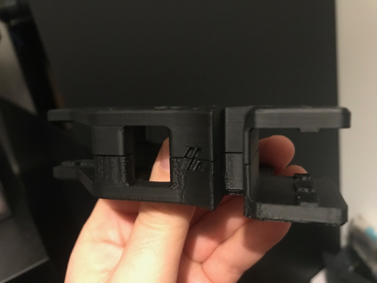
The lower A drive was the first time I have tried to print with ABS. The upper was printed after a few tweaks to my slicer settings and updates to my Marlin firmware configuration. I am now quite happy with the results and will carry on printing the rest of the parts.
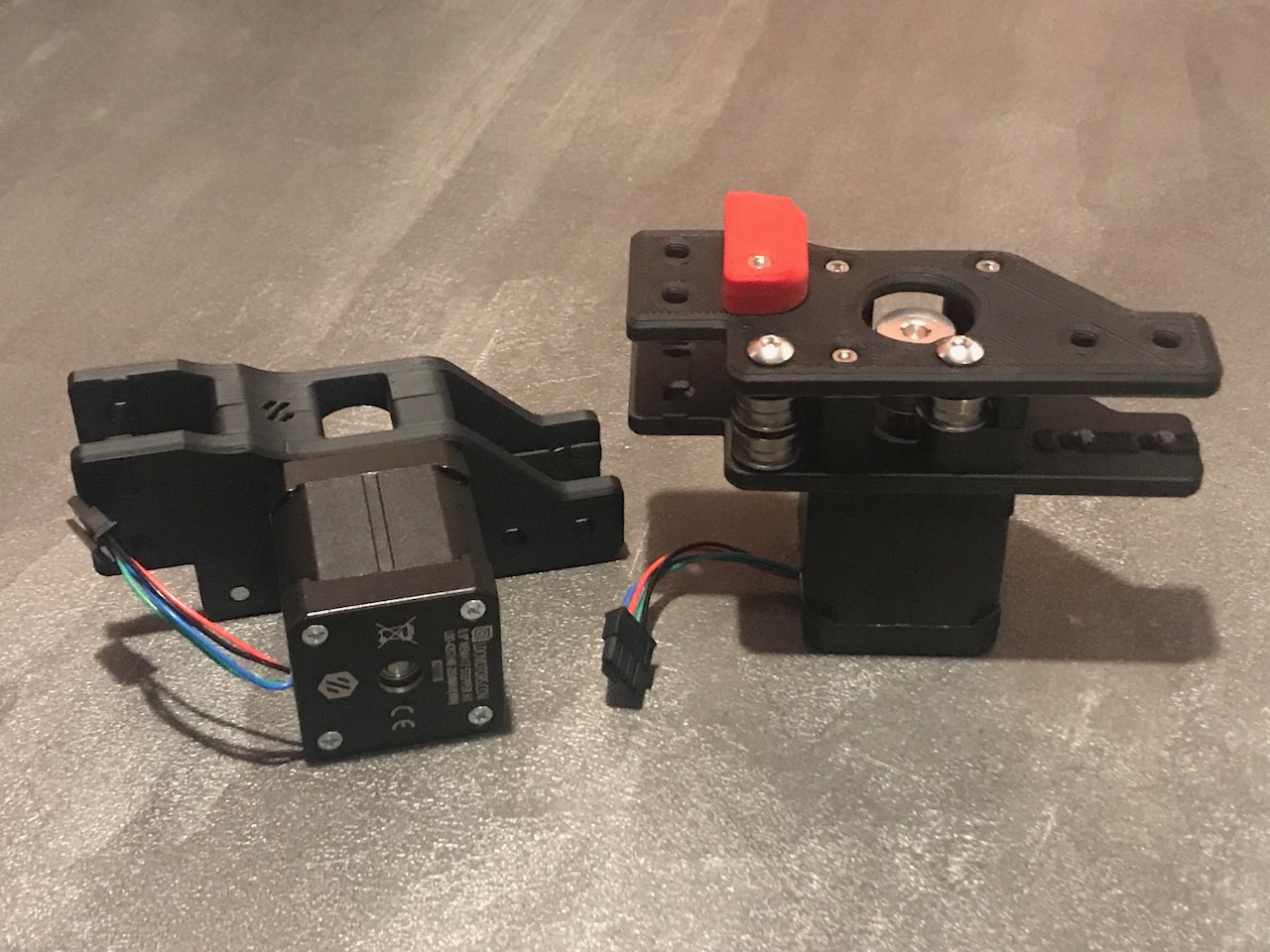
Assembly
Parts Used
| Item | Quantity |
|---|---|
| F695 Bearing | 12 |
| GT2 20T Pulley (5mm ID 6mm W) | 2 |
| M3 Threaded Insert | 1 |
| M3x10 SHCS | 1 |
| M3x30 SHCS | 6 |
| M5 1mm Spacer | 12 |
| M5x30 BHCS | 4 |
| NEMA17 Motor 17HS19-2004S | 2 |
✅ Front Idlers
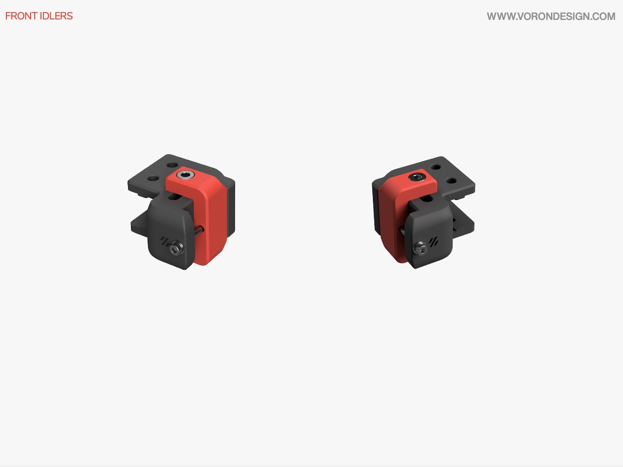
Image © 2020 Voron Design
| Item | Quantity | Material | Size | Weight | Cost | Printed | Notes |
|---|---|---|---|---|---|---|---|
| tensioner_left | 1 | eSun ABS+ (Fire Engine Red) | 2.61m | 6.66g | £0.13 | ✔️ | This is a Trident r1 Part |
| tensioner_right | 1 | eSun ABS+ (Fire Engine Red) | 2.61m | 6.65g | £0.13 | ✔️ | This is a Trident r1 Part |
| front_idler_a | 2 | eSun ABS+ (Black) | 5.19m | 13.22g | £0.25 | ✔️ | This is a Trident r1 Part |
| front_idler_b | 2 | eSun ABS+ (Black) | 3.07m | 7.83g | £0.15 | ✔️ | This is a Trident r1 Part |
Assembly
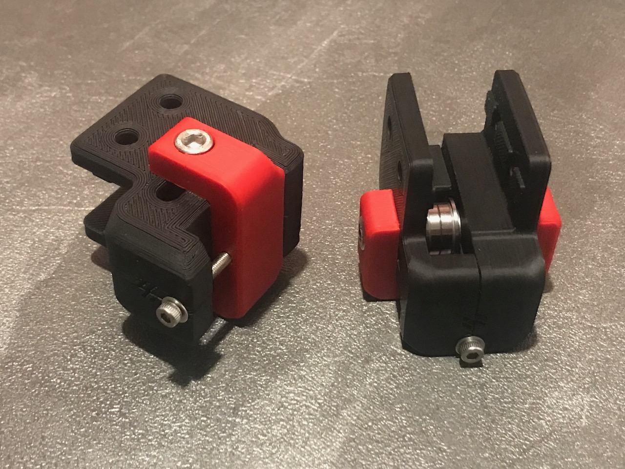
The screws on the front of the idlers move the tensioners forwards and backwards, this allows for easy adjustment of the belt tension.
Parts Used
| Item | Quantity |
|---|---|
| F695 Bearing | 4 |
| M3 Threaded Insert | 2 |
| M3 Washer | 2 |
| M3x40 SHCS | 2 |
| M5 1mm Spacer | 4 |
| M5 Hexnut | 2 |
| M5x40 SHCS | 2 |
✅ Rear Crossbar
Both fully assembled AB Drive Units are required to install the rear crossbar.
Assembly
Parts Used
| Item | Quantity |
|---|---|
| M5 T-nut | 8 |
| M5x10 BHCS | 8 |
| Misumi HFSB5-2020-290 | 1 |
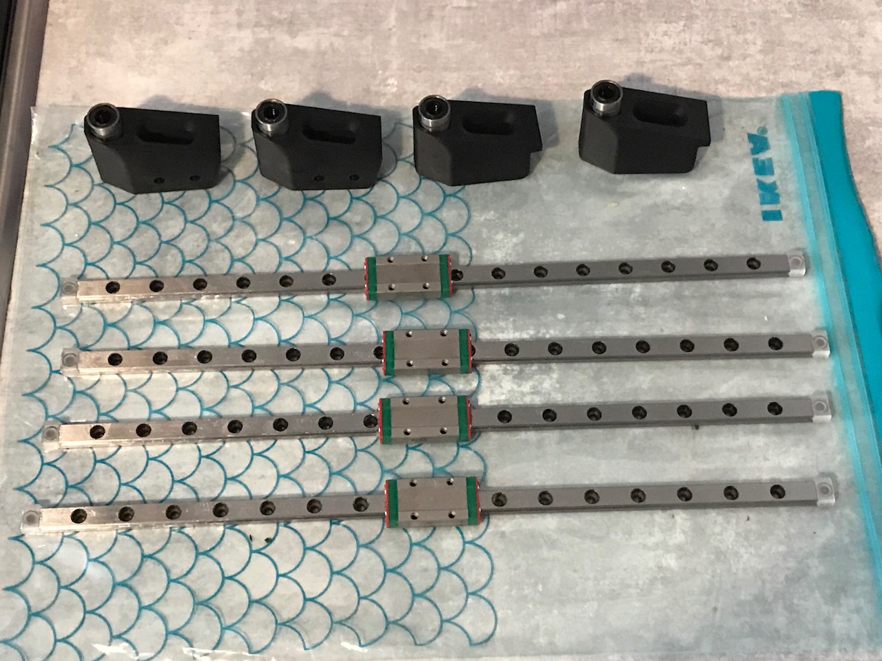
✅ Linear Rails
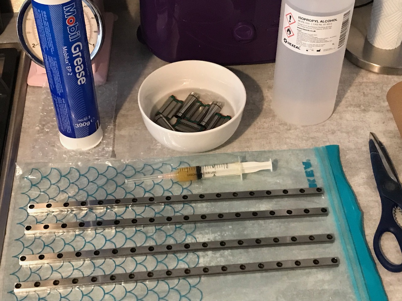
The linear rails come delivered with a coating of oil to prevent rust during storage and shipping. This coating is not a lubricant and needs to be removed before applying a coating of grease to the bearing surfaces.
I carefully removed the carriages from the rails and soaked them in Isopropyl alcohol for a few hours, then let them air dry before applying Mobil EP2 grease with a syringe directly to the ball bearings. I then reassembled the rails and applied more grease through one of the mounting holes behind the carriage.
Assembly
Parts Used
| Item | Quantity |
|---|---|
| Linear Rail MGN9H 350mm | 2 |
| M3 T-nut | 20 |
| M3 Washer | 1 |
| M3x8 SHCS | 18 |
| M3x12 BHCS | 1 |
| M5 T-nut | 14 |
| M5x10 BHCS | 13 |
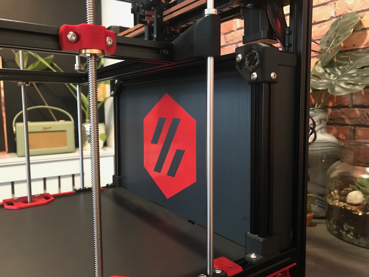
Z Axis
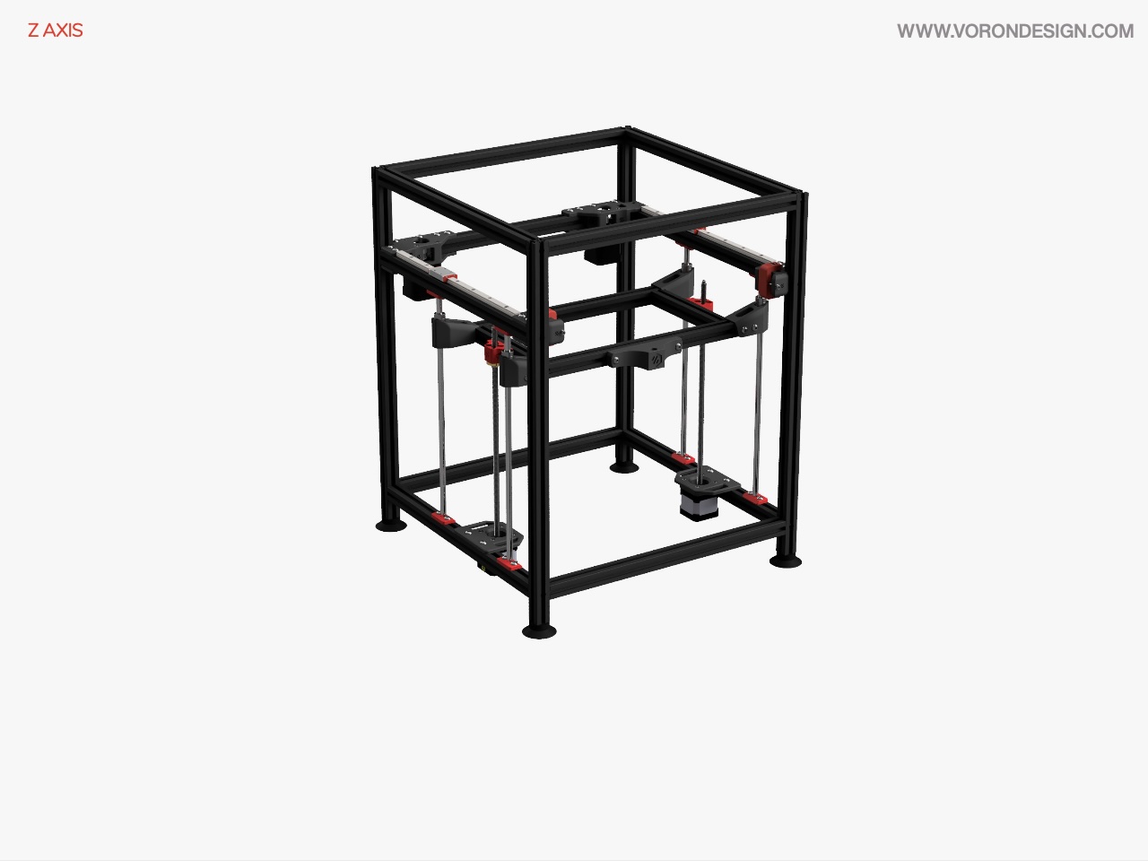
Image © 2020 Voron Design
✅ Bed Frame
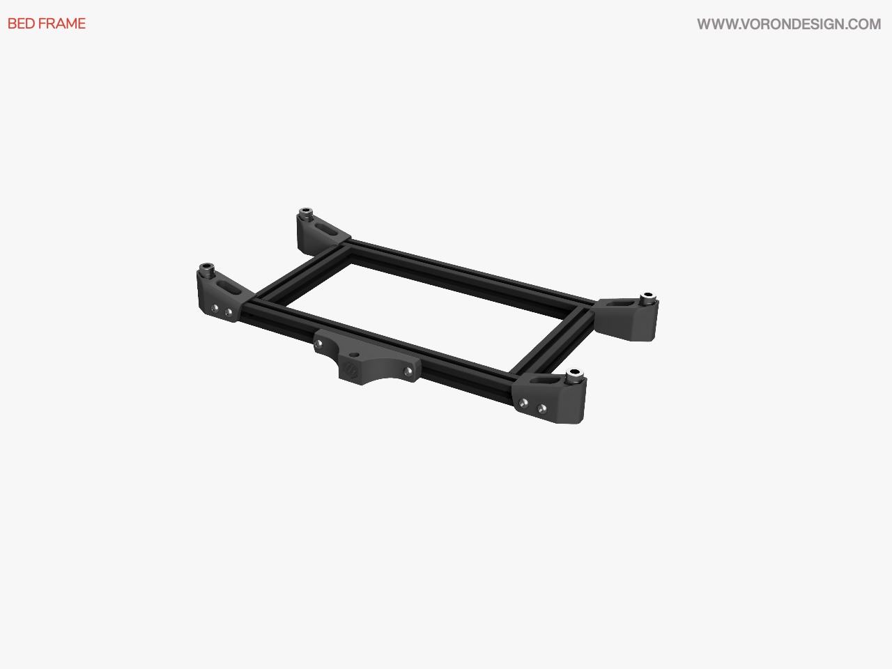
Image © 2020 Voron Design
| Item | Quantity | Material | Size | Weight | Cost | Printed | Notes |
|---|---|---|---|---|---|---|---|
| bed_mount_front | 1 | eSun ABS+ (Fire Engine Red) | 10.22m | 26.05g | £0.49 | ✔️ | Replaced later when mounting the bed |
| z_bearing_block_a | 2 | eSun ABS+ (Black) | 7.09m | 18.07g | £0.34 | ✔️ | |
| z_bearing_block_b | 2 | eSun ABS+ (Black) | 7.09m | 18.07g | £0.34 | ✔️ |
Assembly
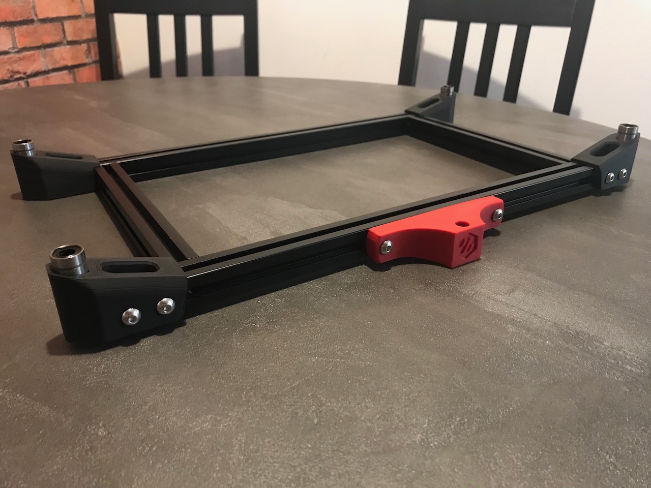
The bed frame will not only hold the bed, but will also be a base for the Z endstop, some Wago mounts to connect the low voltage connections to the endstop and thermistor and the mains connections to the bed, and also Bed Fans to circulate hot air around to heat up the enclosure.
Parts Used
| Item | Quantity |
|---|---|
| LM8LUU Linear Bearing | 4 |
| M5 T-nut | 10 |
| M5x10 BHCS | 8 |
| M5x16 BHCS | 6 |
| Misumi HFSB5-2020-200-TPW | 2 |
| Misumi HFSB5-2020-420-AH45-BH375 | 2 |
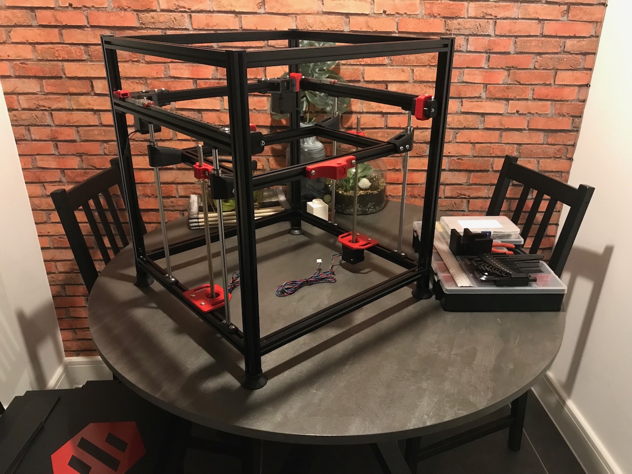
✅ Z Axis Rods
| Item | Quantity | Material | Size | Weight | Cost | Printed | Notes |
|---|---|---|---|---|---|---|---|
| leadscrew_block | 2 | eSun ABS+ (Fire Engine Red) | 3.87m | 9.88g | £0.19 | ✔️ | |
| z_shaft_retainer | 8 | eSun ABS+ (Black) | 0.89m | 2.26g | £0.04 | ✔️ | |
| z_motor_mount | 2 | eSun ABS+ (Fire Engine Red) | 8.50m | 21.68g | £0.41 | ✔️ | |
| z_cable_chain_mount | 1 | ❓ | This is a Trident Part. May need to make some modifications for it to fit and I will need to print ends for the chain |
Assembly
Parts Used
| Item | Quantity |
|---|---|
| Linear Shaft 8x320mm | 4 |
| M3 Nyloc Hexnut | 4 |
| M3x12 SHCS | 12 |
| M5 T-nut | 24 |
| M5x10 BHCS | 20 |
| M5x16 BHCS | 4 |
| NEMA17 TR8x4 300mm Linear Stepper | 2 |
| TR8x4 Leadscrew Nut | 2 |
X Axis
The X Axis was flipped on the Trident (linear rails are on the bottom of the extrusion like the V2, this will not work on the 1.8 as the guide rails are mounted to the bottom of the extrusion too). I had originally wanted to use the Trident toolhead carriage with a single MGN12 linear rail, however due to the changes on the X axis the endstops were moved to the XY Joints not the toolhead. Because of this I wouldn't have anywhere to mount my endstop so I am not using an MGN12 rail here and instead using the dual MGN9s of the original design.
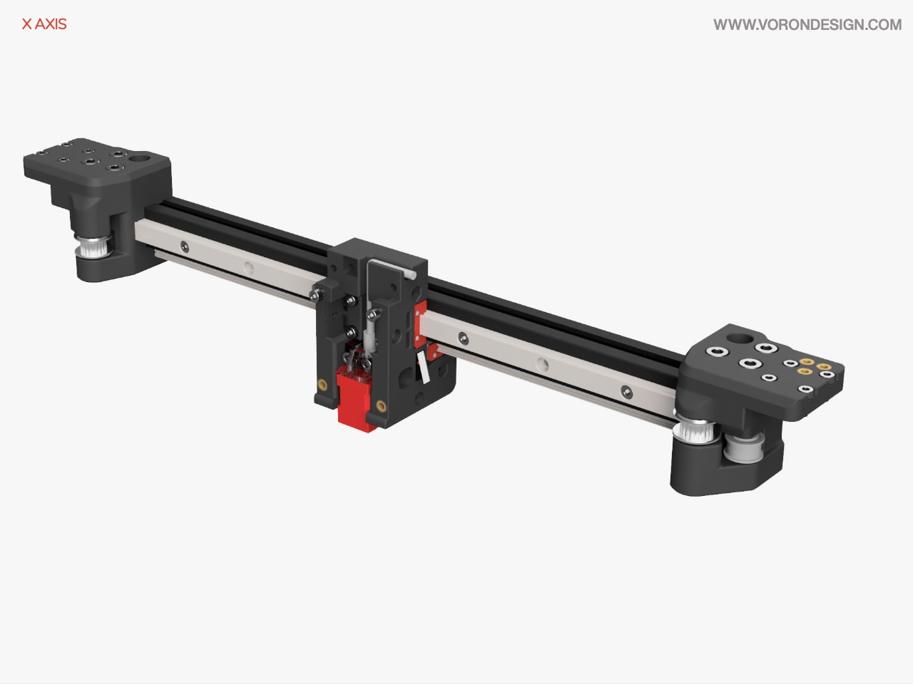
Image © 2020 Voron Design
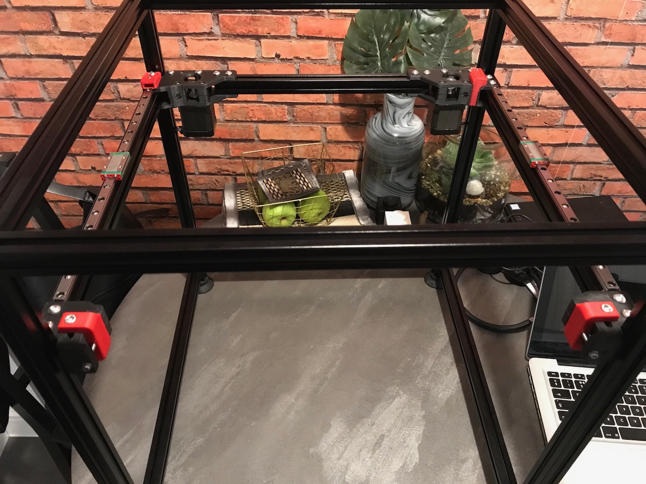
✅ XY Joints
| Item | Quantity | Material | Size | Weight | Cost | Printed | Notes |
|---|---|---|---|---|---|---|---|
| cap | 2 | eSun ABS+ (Black) | 0.12m | 0.30g | £0.01 | ✔️ | |
| xy_joint_left_lower | 1 | eSun ABS+ (Black) | 5.34m | 13.61g | £0.26 | ✔️ | |
| xy_joint_left_upper | 1 | eSun ABS+ (Black) | 10.15m | 25.89g | £0.49 | ✔️ | |
| xy_joint_right_lower | 1 | eSun ABS+ (Black) | 5.71m | 14.55g | £0.28 | ✔️ | |
| xy_joint_right_upper | 1 | eSun ABS+ (Black) | 9.83m | 25.07g | £0.48 | ✔️ | This is the Generic Cable Chain Version |
Assembly
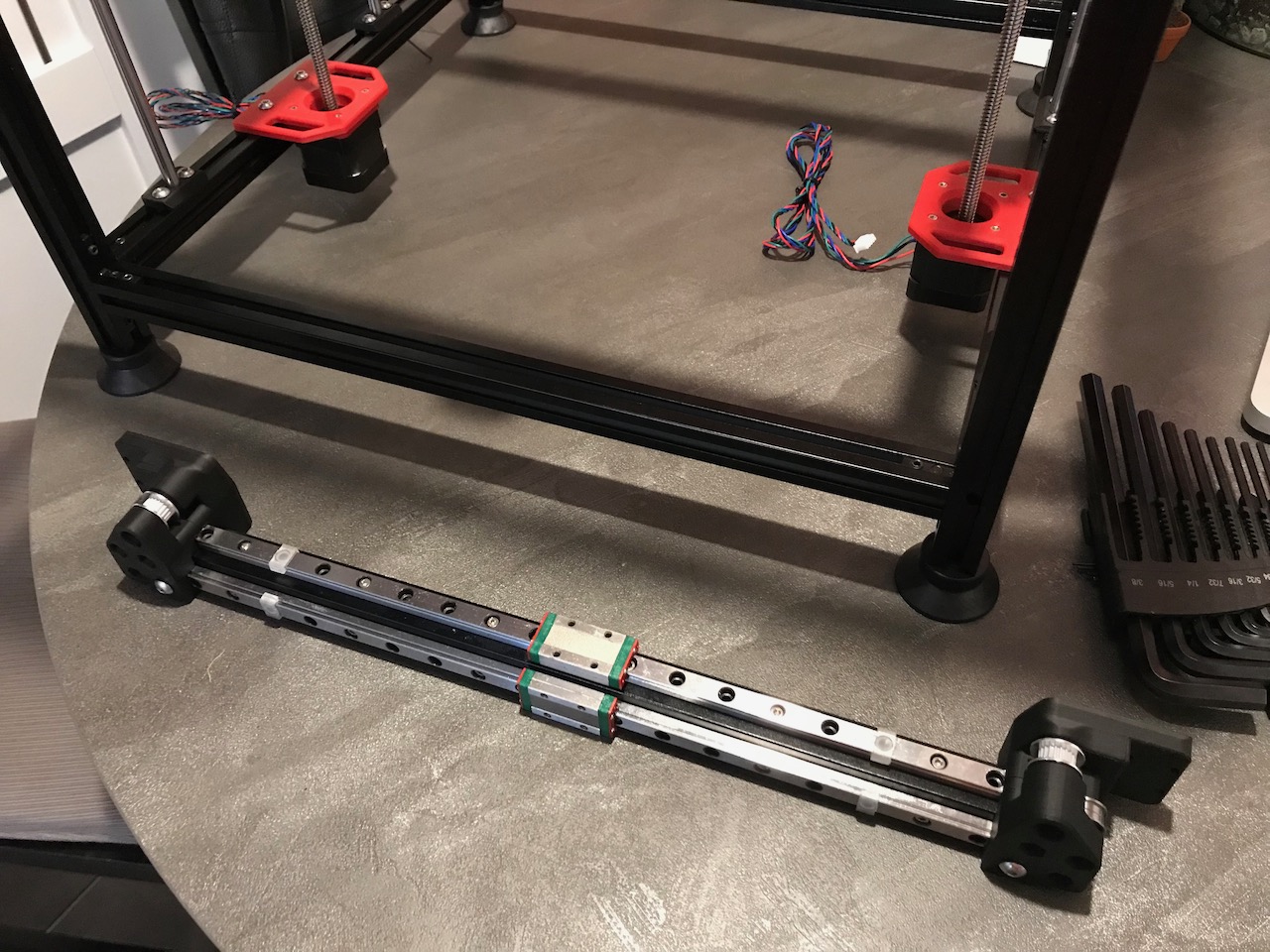
The bolts on the linear rails and the X axis extrusion are left loose at this stage as they will need to be aligned when the X carriage is installed. I have left the little white plastic clips on the rails here so that the blocks do not fall off the ends of the linear rails.
Parts Used
| Item | Quantity |
|---|---|
| F695 Bearing | 4 |
| GT2 20T Toothed Idler (5mm ID 6mm W) | 2 |
| Linear Rail MGN9H 350mm | 2 |
| M3 T-nut | 12 |
| M3 Threaded Insert | 3 |
| M3x8 SHCS | 20 |
| M5 1mm Spacer | 4 |
| M5 Hexnut | 6 |
| M5 T-nut | 4 |
| M5x16 BHCS | 4 |
| M5x30 BHCS | 2 |
| M5x40 SHCS | 6 |
| Misumi HFSB5-2020-380 | 1 |
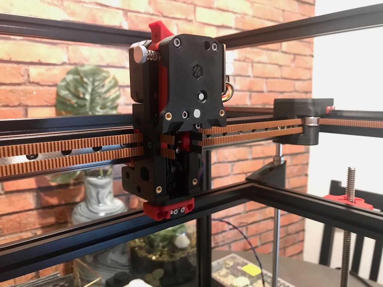
✅ X Carriage
| Item | Quantity | Material | Size | Weight | Cost | Printed | Notes |
|---|---|---|---|---|---|---|---|
| belt_clamp | 2 | eSun ABS+ (Fire Engine Red) | 0.21m | 0.54g | £0.01 | ✔️ | |
| probe_retainer_bracket | 1 | eSun ABS+ (Black) | 0.18m | 0.46g | £0.01 | ✔️ | |
| x_carriage_frame_left | 1 | eSun ABS+ (Black) | 6.86m | 17.48g | £0.33 | ✔️ | |
| x_carriage_frame_right | 1 | eSun ABS+ (Black) | 6.75m | 17.20g | £0.33 | ✔️ | |
| x_carriage_pivot_block | 1 | eSun ABS+ (Black) | 1.25m | 3.19g | £0.06 | ✔️ |
Assembly
The stock design uses an inductive probe in the toolhead, either a PL-08N or an Omron TL-Q5MC2. I do have a XY-08N which is similar to the PL-08N, however, due to the close proximity to the hotend the inductive probe has a tendency to melt. Therefore I have chosen instead to use Klicky Probe.
Parts Used
| Item | Quantity |
|---|---|
| Black 20AWG Silicone Cable (mm) | 300 |
| M2x10 Self-Tapping Screw | 1 |
| M3 Hexnut | 3 |
| M3 Threaded Insert | 6 |
| M3x8 SHCS | 8 |
| M3x10 SHCS | 2 |
| M3x12 SHCS | 2 |
| M3x16 SHCS | 2 |
| M3x30 SHCS | 3 |
| SPDT KW10 Limit Micro Switch | 1 |
✅ Belts
Assembly
The belts are routed in a layout that is known as CoreXY. When one motor rotates the toolhead will move diagonally, when both motors rotate in the same direction the toolhead will move in the X axis and when both motors rotate in opposite directions the toolhead will move in the Y axis.
Parts Used
| Item | Quantity |
|---|---|
| GT2 Open Belt LL-2GT-6 (6mm wide) - 1890mm | 2 |
Afterburner
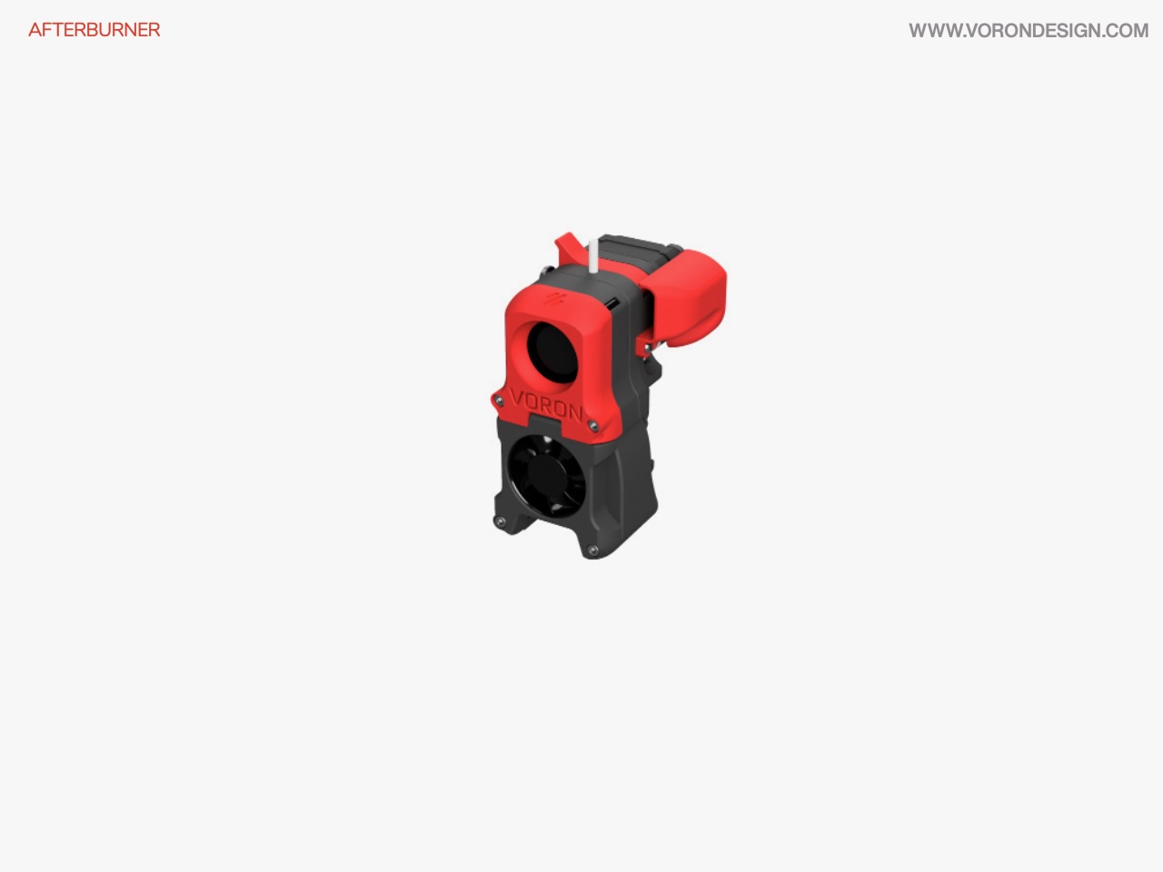
Image © 2020 Voron Design
I built the Afterburner toolhead but will eventually add the StealthBurner Main Body. However, I will keep the original Afterburner extruder, the Clockwork 1 rather than upgrade to Clockwork 2, There are a number of reasons for deciding this:
- I was planning on adding the AB-BN By Badnoob for a larger cooling fan, this was integrated into the design of the StealthBurner.
- I want to add the filament sensor for the Enraged Rabbit Carrot Feeder which is not currently compatible with Clockwork 2.
- I want to add the ERCF Afterburner Toolhead PCB which is also not currently compatible with Clockwork 2.
- The StealthBurner has an integrated mount for an ADXL345 for Klipper Input Shaper.
- The StealthBurner also integrates some cool RGB LEDs (and who doesn't like a bit of RGB?).
Assembly of the parts can be found on its own separate page.
Endstops
✅ Y Endstop
| Item | Quantity | Material | Size | Weight | Cost | Printed | Notes |
|---|---|---|---|---|---|---|---|
| y_endstop_housing | 1 | eSun ABS+ (Fire Engine Red) | 1.47m | 3.74g | £0.07 | ✔️ |
Assembly
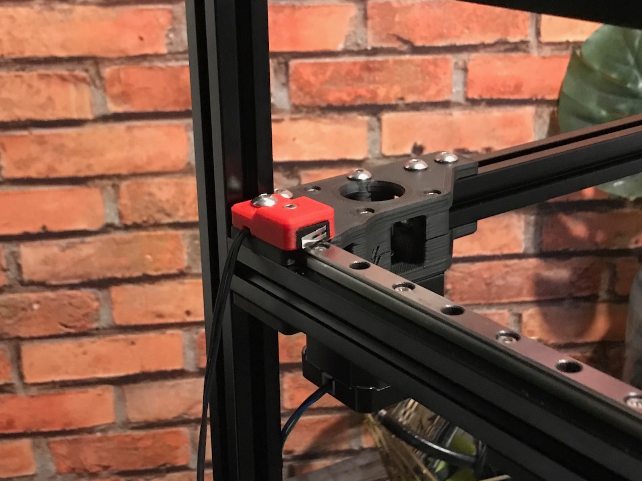
As I am using the Trident A/B Drive Units, I have had to move the Y Endstop to the opposite side of the machine to allow space for the toolhead wires to pass through the wire cover. The side panels will have 1mm foam tape on them and therefore, should allow enough clearance for the endstop wires to tuck between the panel and the outside of the extrusion. The wire will then be bundled with the B Motor wires down into the electronics compartment.
Parts Used
| Item | Quantity |
|---|---|
| 24AWG PTFE Cable (Black) | 500mm |
| M3x16 SHCS | 1 |
| M5x16 BHCS | 1 |
| SPDT KW10 Limit Micro Switch | 1 |
❎ Z Endstop
| Item | Quantity | Material | Size | Weight | Cost | Printed | Notes |
|---|---|---|---|---|---|---|---|
| nozzle_probe | 1 | ❌ |
NOTE: I am not going to print the stock Z endstop, I will replace it with Sexbolt Z Endstop.
Wire Path
✅ Cable Chains
| Item | Quantity | Material | Size | Weight | Cost | Printed | Notes |
|---|---|---|---|---|---|---|---|
| chain_wire_anchor | 2 | eSun ABS+ (Black) | 0.29m | 0.73g | £0.01 | ✔️ | This is a Trident r1 Part |
Assembly
I have applied some Super Lube PTFE grease to the silicone cables inside the cable chains and anchored the cables at each end with cable ties using the chain wire anchors from the Trident r1 update. As I am using multi coloured cables I have also added a bit of cable sleeving over the bare wires between the chains and into the rear electronics compartment these are also held in place with the cable ties at the end of the cable chains, and do not run through the chain.
X Axis Chain
| Item | Quantity |
|---|---|
| 1/2" Braided Cable Sheathing | 150mm |
| 10x11 Cable Chain | 350mm |
| M3 T-nut | 1 |
| M3x8 FHCS | 4 |
| Nylon Cable Ties 4" | 1 |
Y Axis Chain
| Item | Quantity |
|---|---|
| 1/2" Braided Cable Sheathing | 250mm |
| 10x11 Cable Chain | 500mm |
| M3 T-nut | 1 |
| M3x8 FHCS | 4 |
| Nylon Cable Ties 4" | 1 |
Main Toolhead connector
| Item | Quantity |
|---|---|
| 20AWG PTFE Cable (Black) | 2200mm |
| 20AWG PTFE Cable (Red) | 2200mm |
| 20AWG PTFE Cable (White) | 2200mm |
| 24AWG PTFE Cable (Black) | 4400mm |
| 24AWG PTFE Cable (Blue) | 6600mm |
| 24AWG PTFE Cable (Green) | 6600mm |
| 24AWG PTFE Cable (Red) | 2200mm |
| 24AWG PTFE Cable (White) | 4400mm |
| JST XH Connector Plug 2 Position | 5 |
| JST XH Connector Plug 3 Position | 1 |
| JST XH Connector Plug 4 Position | 1 |
| MicroFit3 Connector Plug 14 Position | 1 |
ERCF Connector
| Item | Quantity |
|---|---|
| 24AWG PTFE Cable (Red) | 2200mm |
| 24AWG PTFE Cable (Yellow) | 2200mm |
| JST XH Connector Plug 3 Position | 1 |
| MicroFit3 Connector Plug 2 Position | 1 |
Neopixel Cable
| Item | Quantity |
|---|---|
| 24AWG PTFE Cable (Black) | 2200mm |
| 24AWG PTFE Cable (Red) | 2200mm |
| 24AWG PTFE Cable (Yellow) | 2200mm |
| JST XH Connector Plug 3 Position | 1 |
| MicroFit3 Connector Plug 3 Position | 1 |
✅ Wire Management
It appears that these parts are not specified in the manual, I will use them for the A/B Motor wires and to bring the toolhead wires down to the rear electronics compartment.
| Item | Quantity | Material | Size | Weight | Cost | Printed | Notes |
|---|---|---|---|---|---|---|---|
| wire_anchor | 3 | eSun ABS+ (Black) | 0.65m | 1.65g | £0.03 | ✔️ |
Assembly
Parts Used
| Item | Quantity |
|---|---|
| M3 Hammer Head T-nuts | 6 |
| M3x8 BHCS | 6 |
| Nylon Cable Ties 4" | 6 |
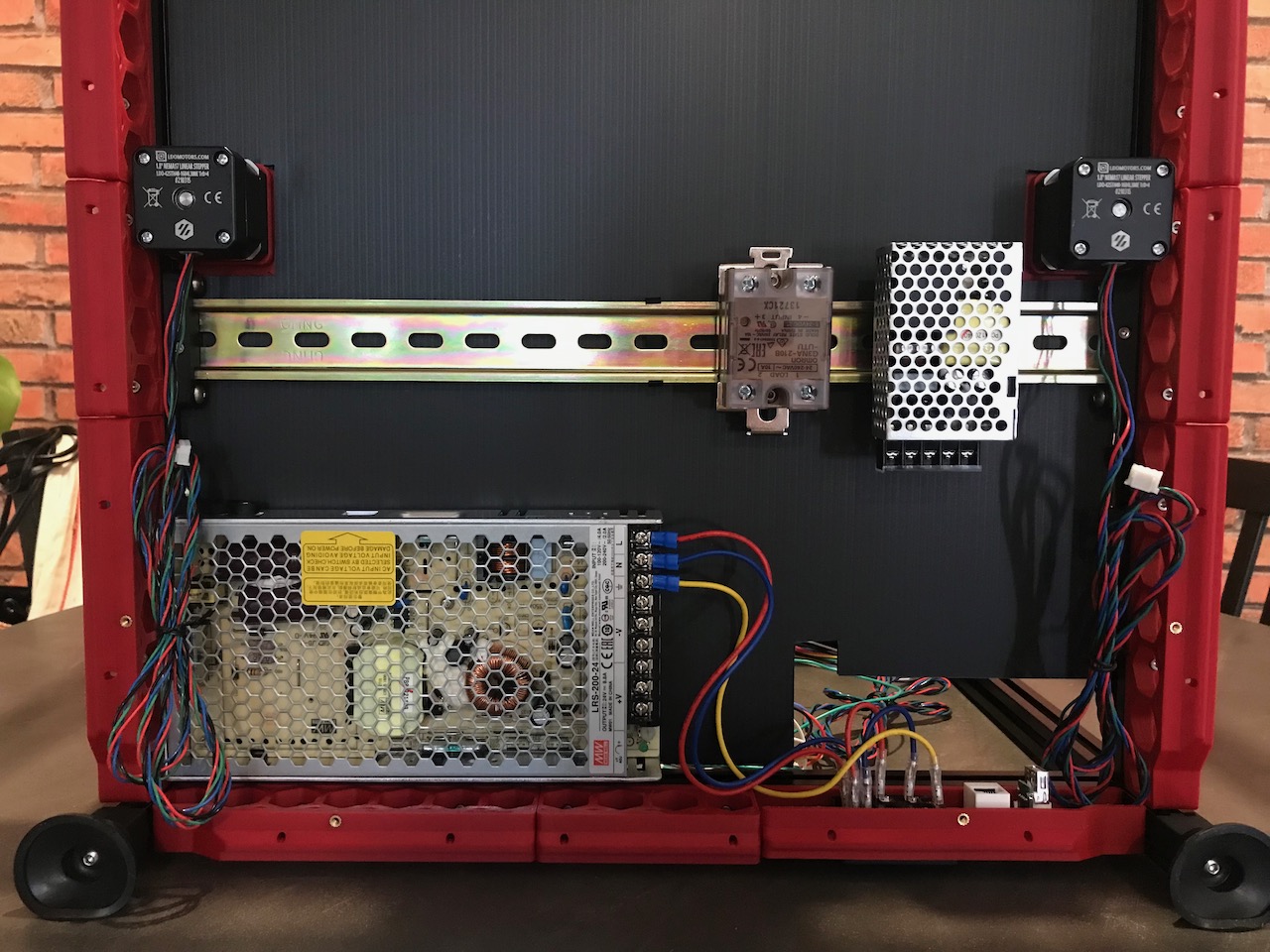
Bottom Compartment
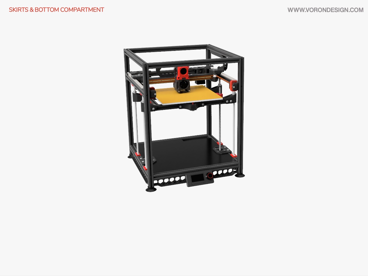
Image © 2020 Voron Design
The bottom compartment is designed to hold the high voltage components such as the main power supply, the power supply for the Raspberry Pi and Neopixel light strips, and Solid State Relay (SSR) for the heated bed. I will also be placing a BigTreeTech 24V UPS module to add capacators across the 24V supply to smooth out the power supplying the MCUs.
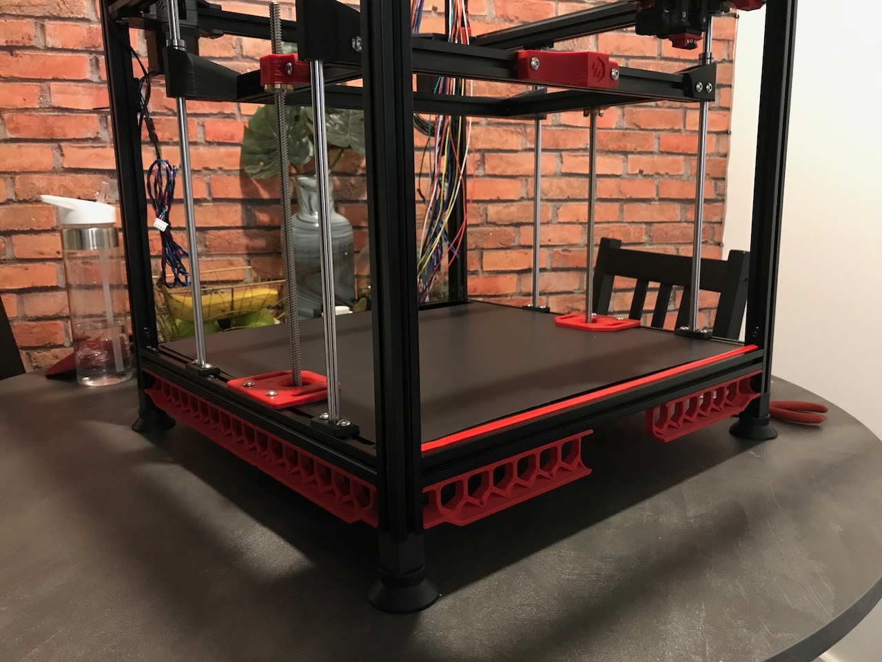
✅ Skirts
| Item | Quantity | Material | Size | Weight | Cost | Printed | Notes |
|---|---|---|---|---|---|---|---|
| keystone_blank_insert | 2 | ❌ | This is a Trident Part. Not required as I am using both keystone spaces | ||||
| skirt_300_left | 3 | eSun ABS+ (Fire Engine Red) | 12.90m | 32.89g | £0.62 | ✔️ | Will be replaced by Mesh Skirts |
| skirt_300_power | 1 | eSun ABS+ (Fire Engine Red) | 12.23m | 31.19g | £0.59 | ✔️ | |
| skirt_300_right | 4 | eSun ABS+ (Fire Engine Red) | 12.92m | 32.95g | £0.63 | ✔️ | Will be replaced by Mesh Skirts |
| skirt_middle | 3 | eSun ABS+ (Fire Engine Red) | 7.49m | 19.11g | £0.36 | ✔️ | Will be replaced by Mesh Skirts |
| foot_spacer | 4 | eSun ABS+ (Black) | 2.28m | 5.82g | £0.11 | ✔️ | This is a 1.6 Part. Required to raise the printer up and allow Display Mount to swivel. |
Assembly
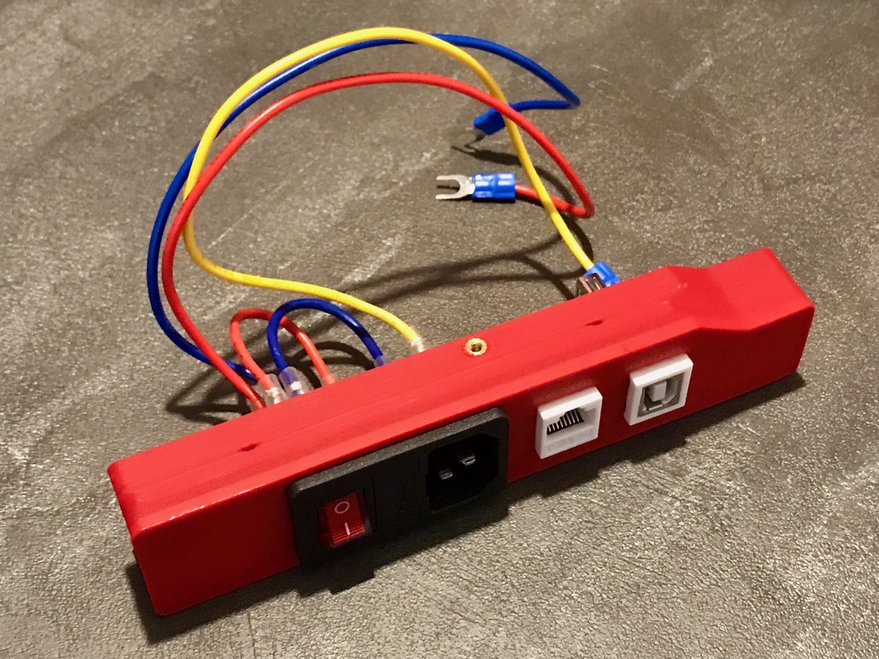
Before attaching the power skirt to the printer the power socket and Keystone inserts are installed into the part.
Parts Used
| Item | Quantity |
|---|---|
| Inlet Power Socket IEC320 C14 | 1 |
| M3 T-nut | 22 |
| M3x8 SHCS | 22 |
| Keystone CAT6 Insert | 1 |
| Keystone USB Insert | 1 |
| M3 Threaded Insert | 8 |
❎ Display Module
| Item | Quantity | Material | Size | Weight | Cost | Printed | Notes |
|---|---|---|---|---|---|---|---|
| mini12864_arm | 2 | eSun ABS+ (Black) | 1.74m | 4.45g | £0.08 | ✔️ | Will swap for Display Mount |
| mini12864_case_back | 1 | eSun ABS+ (Black) | 5.40m | 13.76g | £0.26 | ✔️ | I have modified the mounting holes for this to make them closer together so that the Display Mount Arms will fit between the skirts |
| mini12864_case_front | 1 | eSun ABS+ (Black) | 4.92m | 12.54g | £0.24 | ✔️ | Will use this instead of Display Mount Front as it has been modified to allow the doors to open correctly |
NOTE: I will replace the stock display arms with Display Mount.
✅ Bottom Electronics Mounting
| Item | Quantity | Material | Size | Weight | Cost | Printed | Notes |
|---|---|---|---|---|---|---|---|
| cable_frame_anchor | 5 | eSun ABS+ (Black) | 0.27m | 0.68g | £0.01 | ✔️ | This is a Trident Part |
| DIN_center_support | 3 | eSun ABS+ (Black) | 0.30m | 0.77g | £0.01 | ✔️ | This is a Trident Part |
| DIN_frame_mount | 2 | eSun ABS+ (Black) | 2.57m | 6.54g | £0.12 | ✔️ | This is a Trident Part |
Assembly
Parts Used
| Item | Quantity |
|---|---|
| Coroplast Sheet - 420x420x4 mm | 1 |
| DIN 3 Rails (35mm W) - 420mm | 1 |
| M3x8 SHCS | 2 |
| M5 T-nut | 4 |
| M5x16 BHCS | 4 |
✅ Bottom Electronics Brackets
| Item | Quantity | Material | Size | Weight | Cost | Printed | Notes |
|---|---|---|---|---|---|---|---|
| psu_brace | 1 | eSun ABS+ (Black) | 0.97m | 2.46g | £0.05 | ✔️ | |
| psu_mount_clip | 2 | eSun ABS+ (Black) | 0.87m | 2.21g | £0.04 | ✔️ | |
| rs25_psu_bracket | 1 | eSun ABS+ (Black) | 2.29m | 5.84g | £0.11 | ✔️ | This is a Trident Part |
Assembly
Parts Used
| Item | Quantity |
|---|---|
| DIN Rail Mount Bracket for G3A SSR | 1 |
| M3x6 BHCS | 2 |
| M4x6 BHCS | 5 |
| M5 T-nut | 1 |
| M5x10 BHCS | 1 |
| Mean Well LRS-200-24 PSU | 1 |
| Mean Well RS-25-5 PSU | 1 |
| Omron G3A-210B-DC5 SSR | 1 |
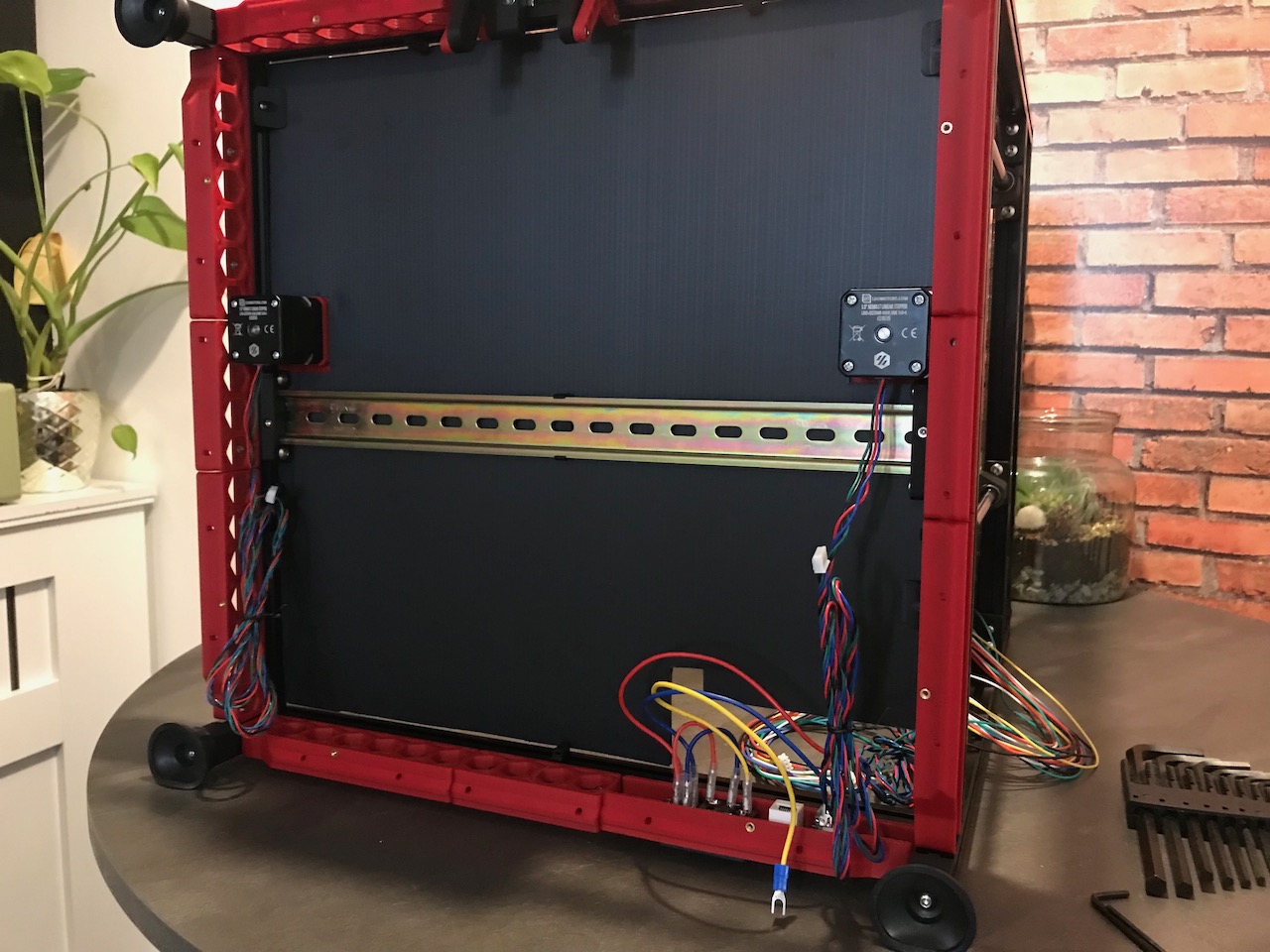
Electronics Compartment
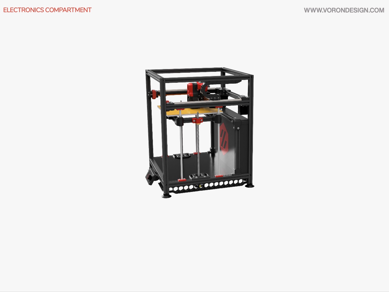
Image © 2020 Voron Design
The rear electronics compartment is designed to house the low voltage components for the printer. The compartment was removed from the 1.8's successor the Trident, however I wanted to have the separation between the low and high voltage components and also wanted space to expand and add additional compenents without being restricted to the space beneath the printer.
✅ Rear Electronics Enclosure
| Item | Quantity | Material | Size | Weight | Cost | Printed | Notes |
|---|---|---|---|---|---|---|---|
| base_left | 1 | eSun ABS+ (Black) | 3.48m | 8.88g | £0.17 | ✔️ | |
| base_right | 1 | eSun ABS+ (Black) | 3.48m | 8.88g | £0.17 | ✔️ | |
| corner_bracket_left | 1 | eSun ABS+ (Black) | 11.06m | 28.21g | £0.54 | ✔️ | |
| corner_bracket_right | 1 | eSun ABS+ (Black) | 11.06m | 28.21g | £0.54 | ✔️ | |
| din_bracket_base | 4 | eSun ABS+ (Black) | 0.60m | 4.08g | £0.08 | ✔️ | |
| din_bracket_clamp | 4 | eSun ABS+ (Black) | 1.31m | 3.33g | £0.06 | ✔️ | |
| panel_holder | 2 | ❌ | Will replace these with front_panel_rest | ||||
| wire_cover_left | 1 | ❓ | This is a Trident r1 Part. I may need to make some modifications to this to make it fit. | ||||
| wire_cover_right | 1 | ❓ | This is a Trident r1 Part. I may need to make some modifications to this to make it fit. |
Assembly
The manual says to install the DIN Rails after fitting the enclosure. I found it easier to add the DIN rails to the enclosure and afterwards install the assembly to the frame.
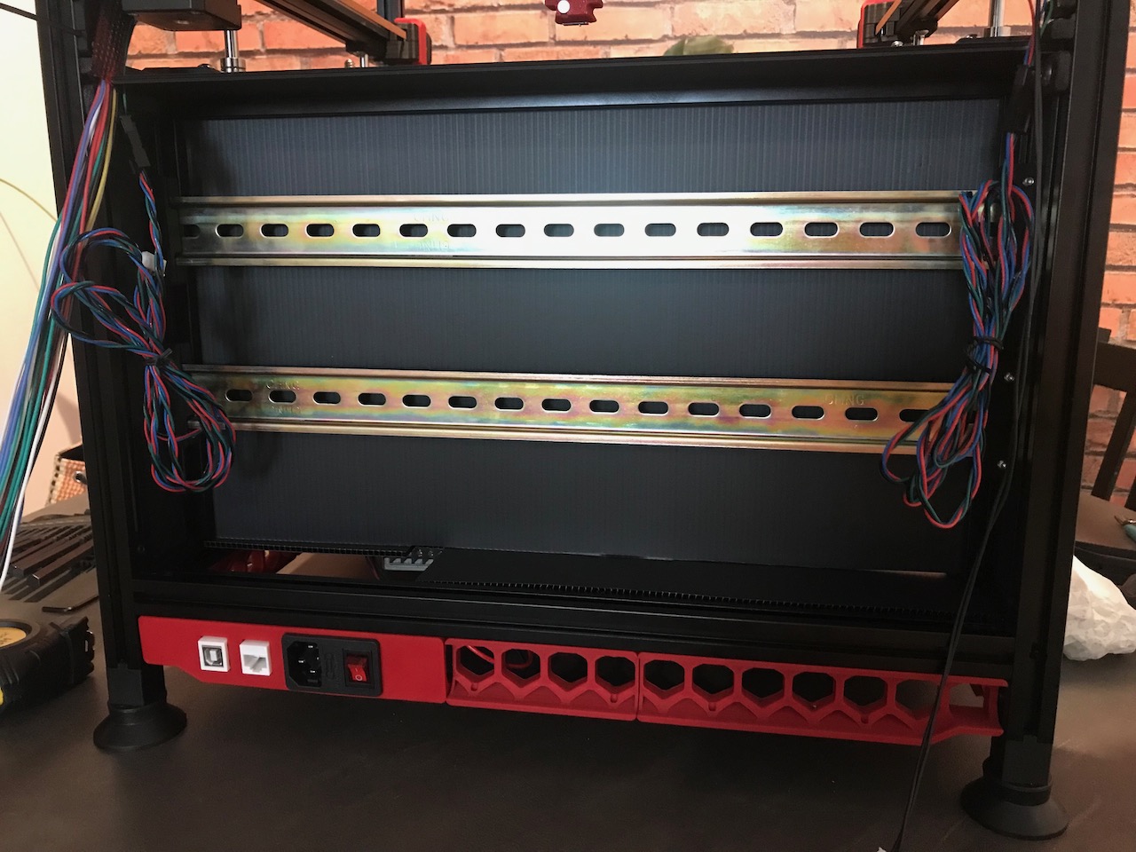
I have also purchased an additional DIN rail than what was specified on the BOM as the manual displays 2 installed and it will give the flexability to place additional components in the rear of the printer.
Parts Used
| Item | Quantity |
|---|---|
| Coroplast Sheet - 236x415x4 mm | 1 |
| Coroplast Sheet - 242x46x4 mm | 2 |
| Coroplast Sheet - 419x66x4 mm | 1 |
| DIN 3 Rails (35mm W) - 420mm | 2 |
| M3 T-nut | 8 |
| M3x16 BHCS | 8 |
| M5 T-nut | 12 |
| M5x10 SHCS | 12 |
| Misumi HFSB5-2020-230 | 2 |
| Misumi HFSB5-2020-420 | 1 |
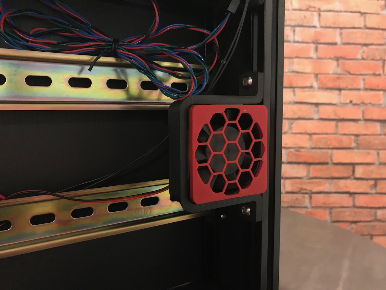
🔧 Rear Electronics Brackets
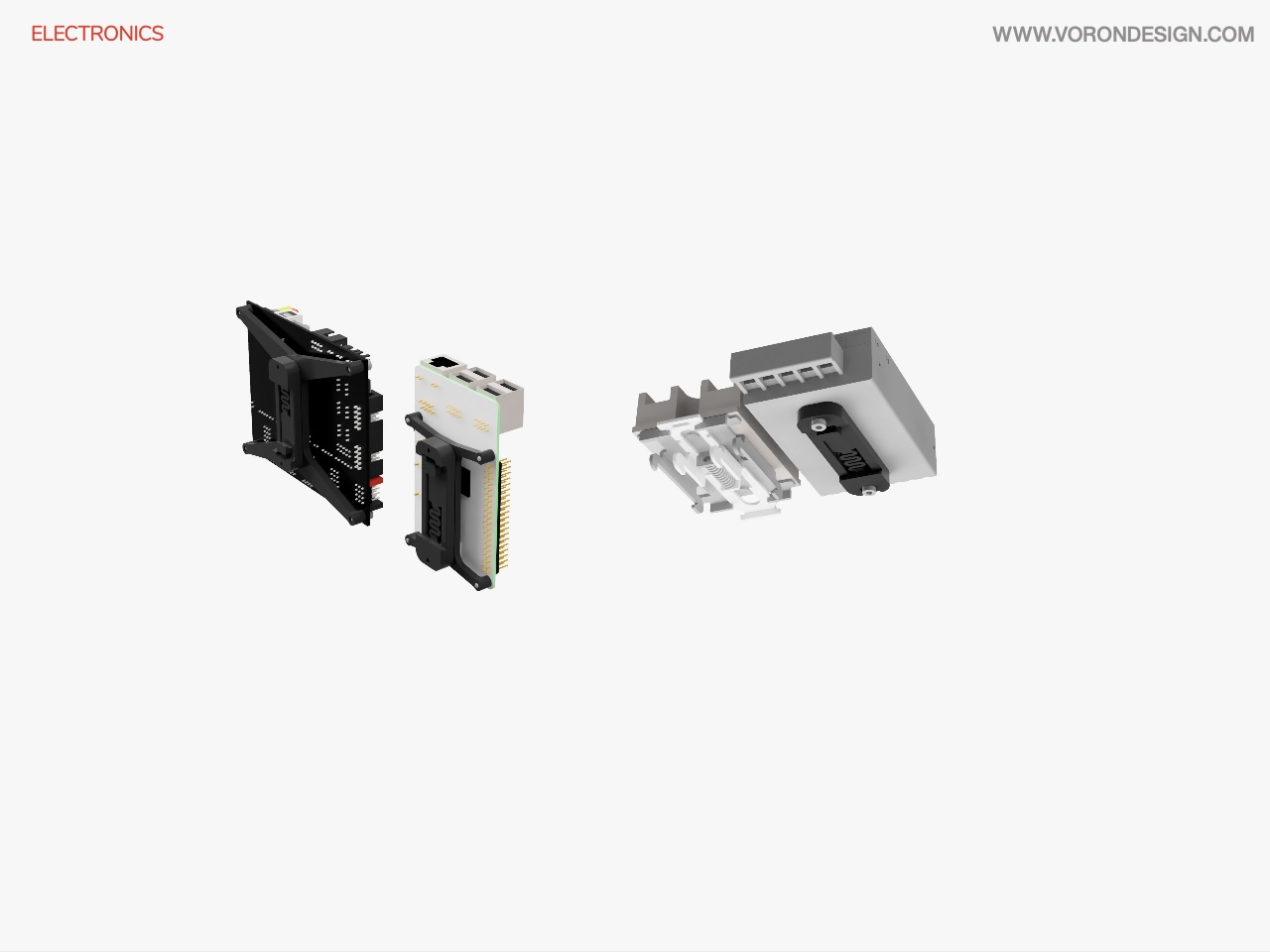
Image © 2020 Voron Design
I managed purchase a SKR 1.4 (the non Turbo verion) cheaply to replace the SKR 1.4 Turbo I have in my Anet A8 and planed to install the SKR 1.4 Turbo here. I chose this to enable me to swap the boards with minimal re-wiring, and without the need to re-print a new case for my Anet A8. I have also purchased the BTT EXP-MOT motor expansion module to allow me to install additional stepper motor drivers to run the Enraged Rabbit Carrot Feeder and potentially add a 3rd Z Stepper Motor.
| Item | Quantity | Material | Size | Weight | Cost | Printed | Notes |
|---|---|---|---|---|---|---|---|
| controller_fan_guard | 1 | eSun ABS+ (Fire Engine Red) | 1.80m | 4.59g | £0.09 | ✔️ | |
| controller_fan_mount | 1 | eSun ABS+ (Black) | 5.44m | 13.88g | £0.26 | ✔️ | |
| pcb_din_clip | 4 | eSun ABS+ (Black) | 1.51m | 3.84g | £0.07 | 3 | This is a Trident r1 Part. 2 for SKR 1.4 Turbo, 1 for BTT MOT and 1 for Raspberry Pi |
| raspberrypi_bracket | 1 | eSun ABS+ (Black) | 1.77m | 4.51g | £0.09 | ✔️ | This is a Trident Part. Going to replace with LDO Beefy Raspberry Pi Bracket |
| BTT_MOT_EXP_bracket | 1 | eSun ABS+ (Black) | 1.76m | 4.48g | £0.09 | ✔️ | This is a Trident Part. |
| SKR_bracket_inline_set | 1 | eSun ABS+ (Black) | 2.55m | 6.49g | £0.12 | ✔️ | This is a Trident Part. |
| Raspberry_Pi | 1 | eSun ABS+ (Black) | ❌ | From the Voron Parts Repository | |||
| din_clip | 1 | eSun ABS+ (Black) | ❌ | From the Voron Parts Repository |
Assembly
Parts Used
| Item | Quantity |
|---|---|
| 3M VHB Tape 5952 | 1 |
| M2x10 Self-Tapping Screw | 10 |
| M3x6 BHCS | 4 |
| M5 Hammer Head T-nuts | 2 |
| M5x10 BHCS | 2 |
✅ Electronics Panel
| Item | Quantity | Material | Size | Weight | Cost | Printed | Notes |
|---|---|---|---|---|---|---|---|
| front_panel_rest | 2 | eSun ABS+ (Black) | 9.53m | 24.29g | £0.46 | ✔️ | For Voron 2.2. Will swap out panel_holder for these at rear of printer |
| latch_left | 1 | eSun ABS+ (Fire Engine Red) | 0.19m | 0.48g | £0.01 | ✔️ | |
| latch_right | 1 | eSun ABS+ (Fire Engine Red) | 0.19m | 0.48g | £0.01 | ✔️ | |
| lever_left | 1 | eSun ABS+ (Fire Engine Red) | 0.41m | 1.05g | £0.02 | ✔️ | |
| lever_right | 1 | eSun ABS+ (Fire Engine Red) | 0.41m | 1.05g | £0.02 | ✔️ | |
| lock_body | 2 | eSun ABS+ (Black) | 1.70m | 4.33g | £0.08 | ✔️ |
Assembly
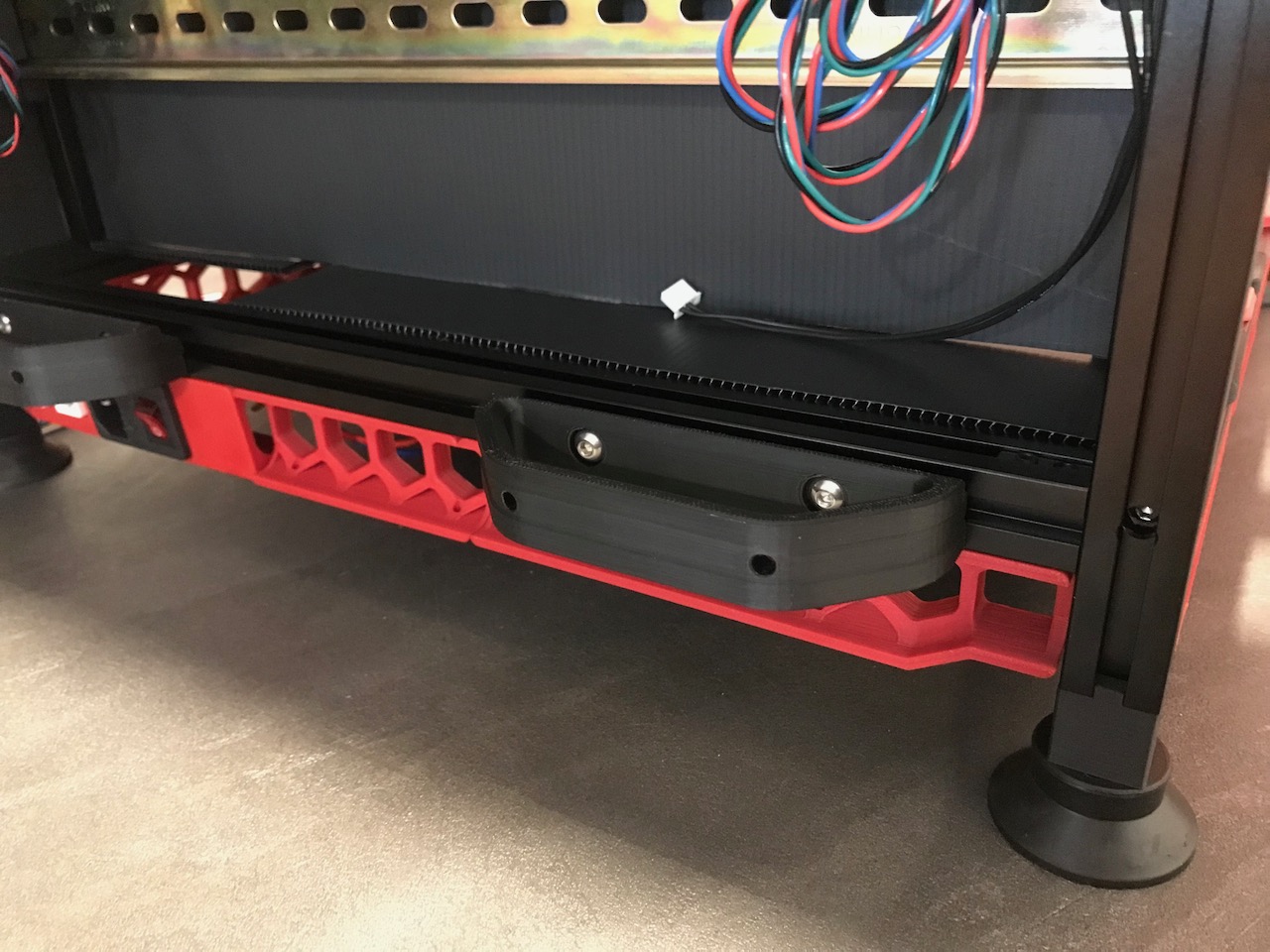
The Electronics Compartment has a couple of parts to rest the elecronics panel on called panel_holders I have replaced these with the front handles from the 2.2 to enable me to move the printer about a little easier and to also keep a little bit of space behind the printer to allow the electronics compartment fan to breathe.
I also plan on installing the Klipper Expander in the space at the bottom of the electronics compartment just above the handle shown.
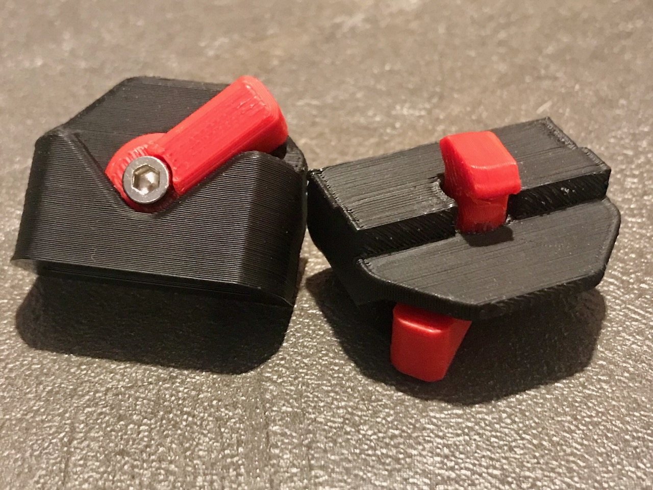
The V1.8 has 3D printed locks to hold on the back panel; This makes accessing the electronics easy as installing and removing it is completely tool free.
Parts Used
| Item | Quantity |
|---|---|
| Coroplast Sheet - 246x434x4 mm | 1 |
| M3x8 SHCS | 2 |
| M5 T-nut | 4 |
| M5x10 SHCS | 4 |
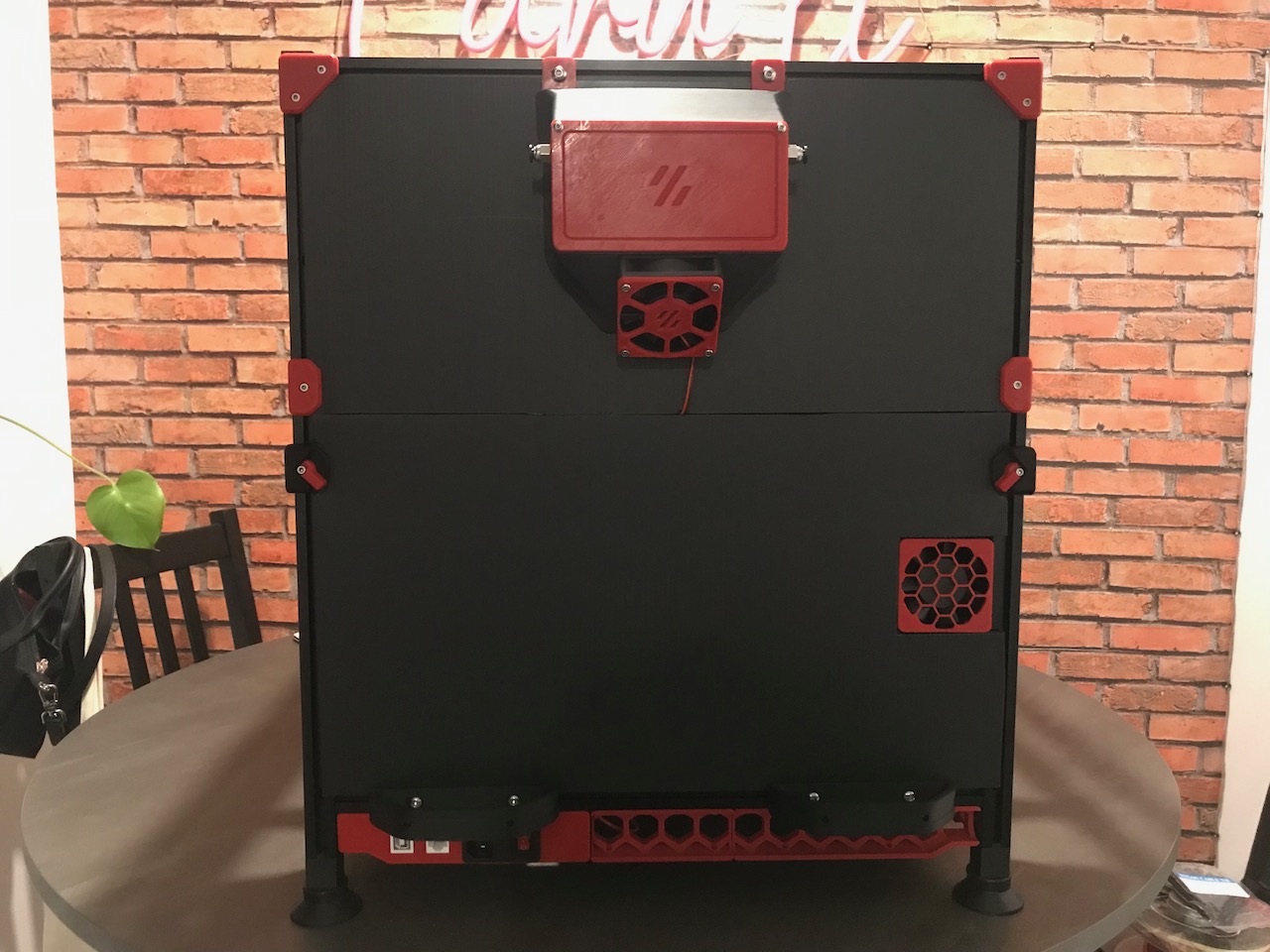
Rear Panel and Exhaust
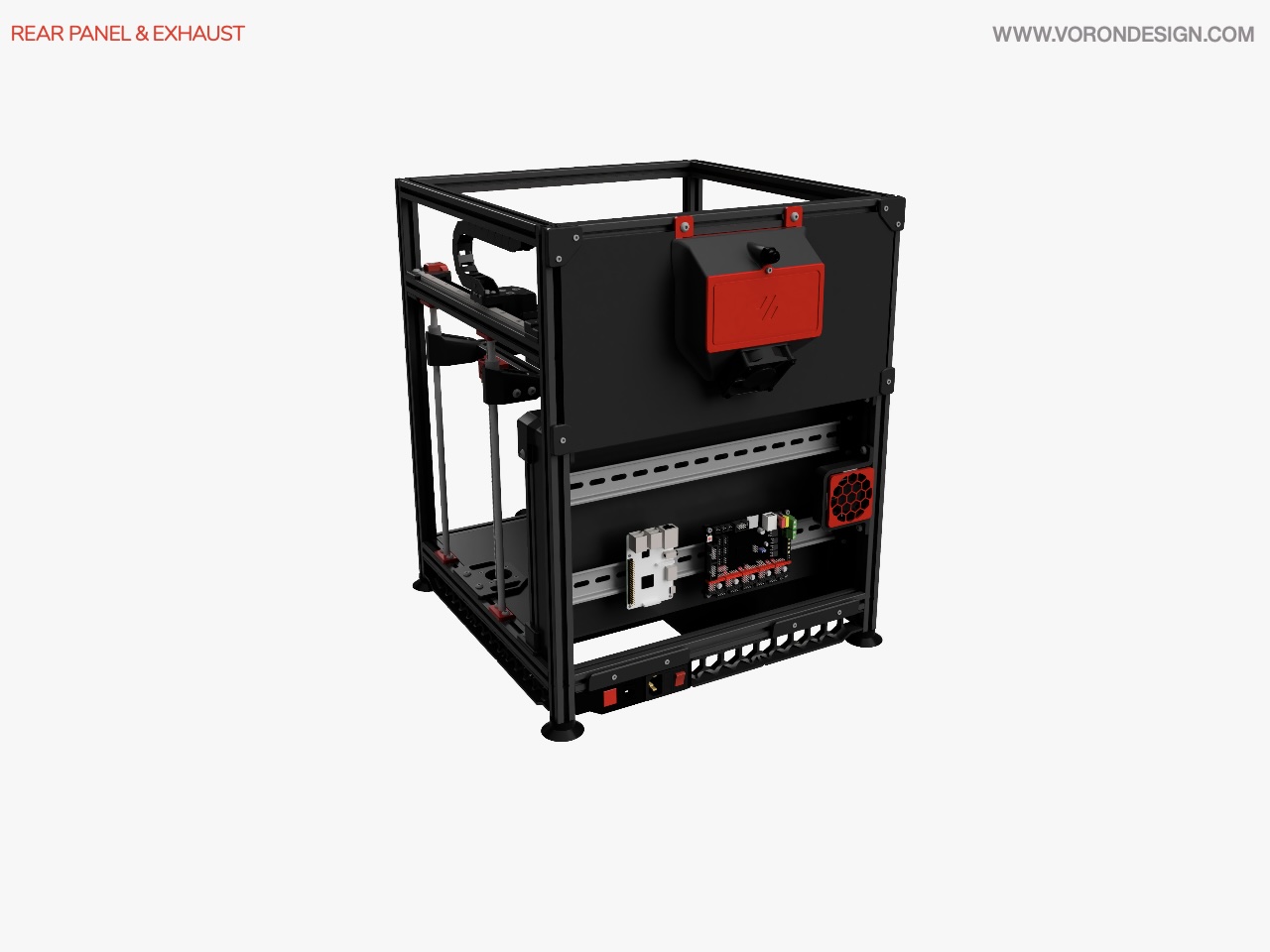
Image © 2020 Voron Design
❎ Exhaust Filter
| Item | Quantity | Material | Size | Weight | Cost | Printed | Notes |
|---|---|---|---|---|---|---|---|
| exhaust_fan_grill | 1 | eSun ABS+ (Fire Engine Red) | 2.08m | 5.30g | £0.10 | ✔️ | This is a 2.4 Part |
| filter_access_cover | 1 | Amazon Basics PETG (Red) | ✔️ | Will replace with Exhaust Mount Side Entry printed in ABS | |||
| exhaust_filter_grill | 1 | Amazon Basics PETG (Red) | ✔️ | Will replace with Magnetic Grill Cover printed in ABS | |||
| exhaust_filter_housing | 1 | Tinmorry PETG (Black) | ✔️ | Will replace with Exhaust Mount Side Entry printed in ABS | |||
| exhaust_filter_mount | 2 | eSun ABS+ (Fire Engine Red) | 0.81m | 2.06g | £0.04 | ✔️ |
Assembly
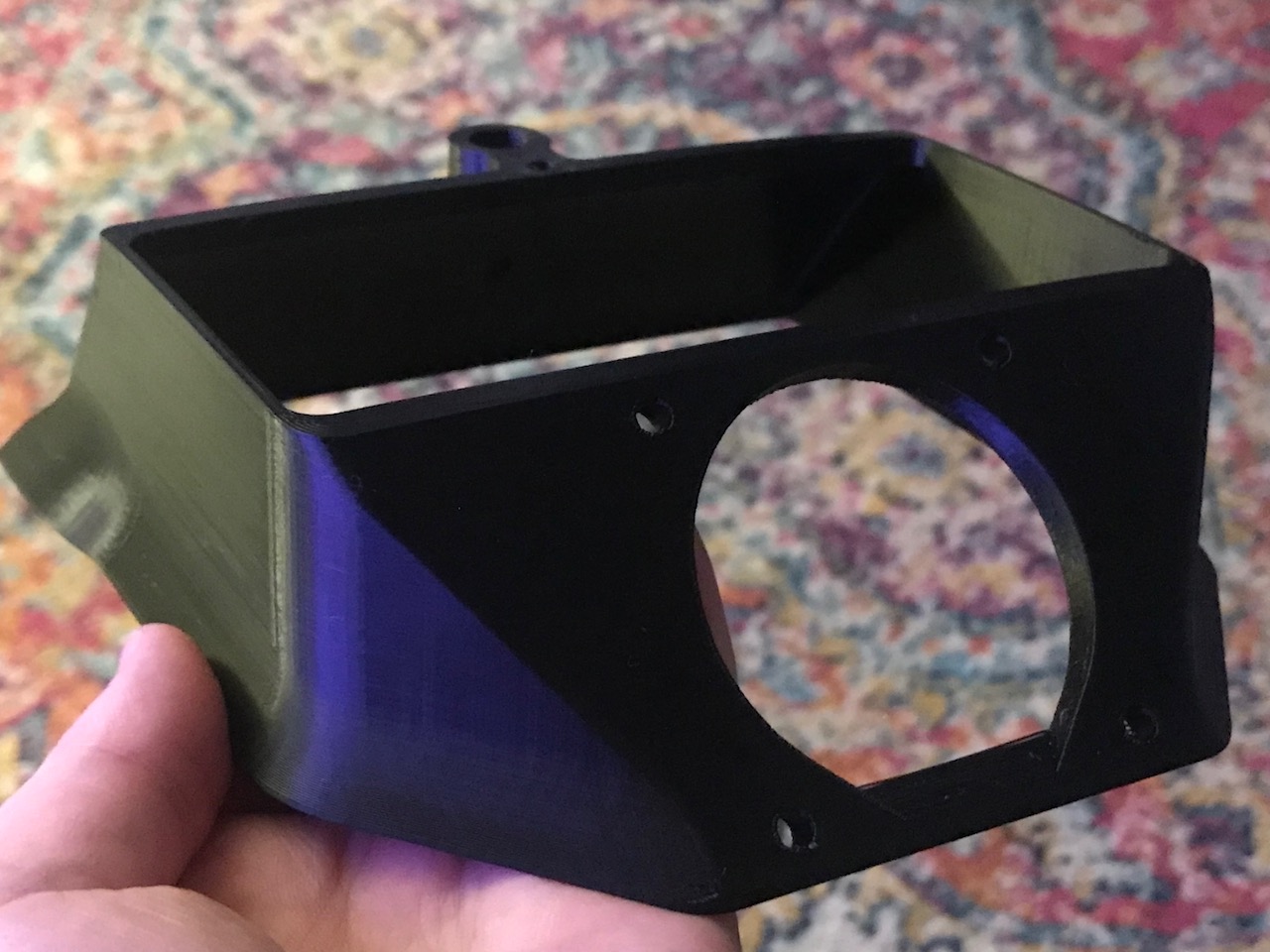
I originally printed this in PETG that would be fitted to my HyperCube upgrade. I will replace with the Exhaust Mount Side Entry mod to allow me to pass 2 bowden tubes through to experiment with a dual bowden setup using 2 M4 extruders.
Heated Bed
| Item | Quantity | Material | Size | Weight | Cost | Printed | Notes |
|---|---|---|---|---|---|---|---|
| bed_mount_front | 1 | eSun ABS+ (Fire Engine Red) | 11.89m | 30.31g | £0.56 | ✔️ | I modified this part to fit my off spec bed |
✅ Print Surface
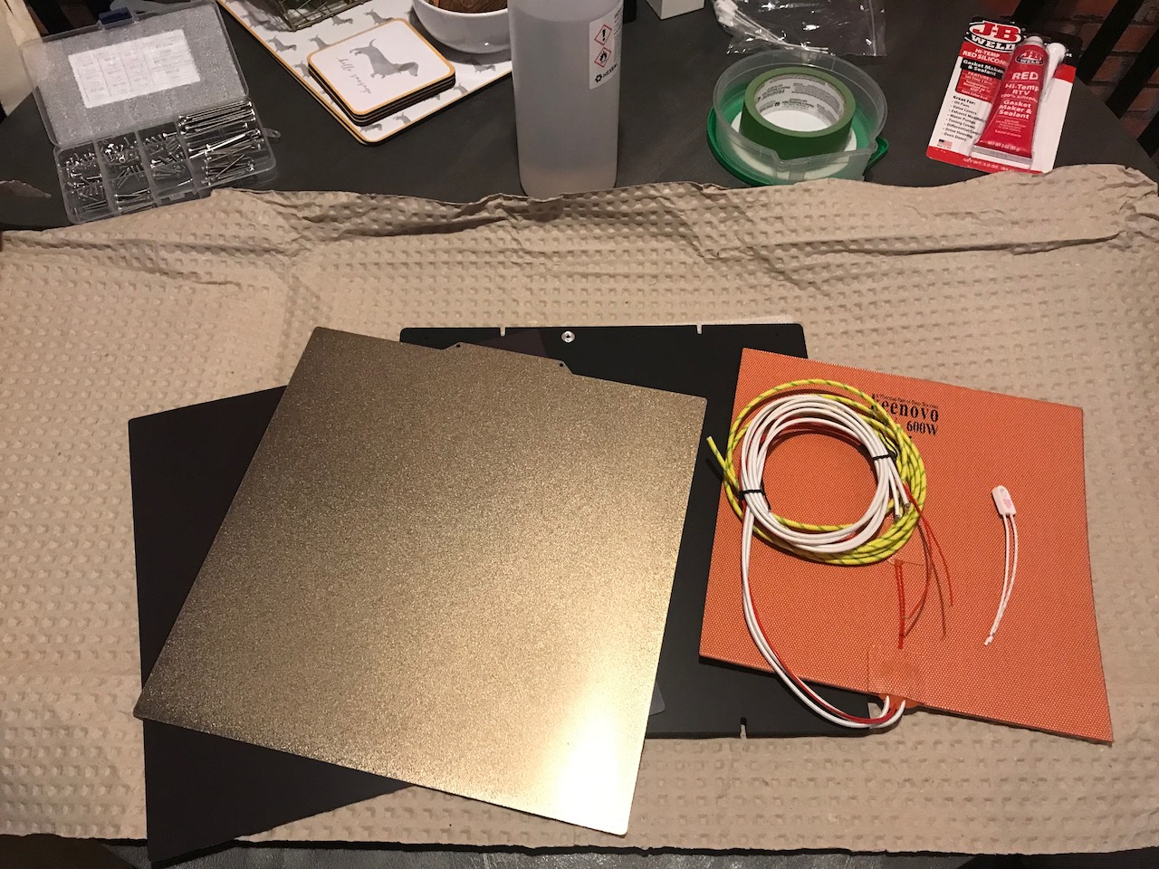
Assembly
I cleaned the Aluminium Tooling plate on both sides, thouroughly with Isopropyl alcohol and ensured it was completely dry before peeling a small portion of the adhesive backing from the magnet for the spring steel sheet.
I then carefully lined up the magnet to the center of the top of the tooling plate, and pressed it down making sure to press from the center outwards to remove any air bubbles, pulled back some more of the backing and repeated until the magnet has been applied.
Once the magnet was applied I used a 3mm drill bit from the undersde of the tool plate to make holes for the mounting screws and then used a craft knife to make space for the screw heads and tidied up using a de-burring tool to remove any sharp edges.
Parts Used
| Item | Quantity |
|---|---|
| 3M 468MP Adhesive Sheet - 12"x12" | 1 |
| PEI 0.04" Sheet - 12"x12" | 1 |
✅ Heater Mat
Assembly
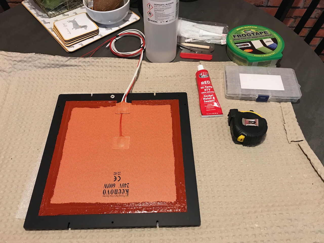
I flipped over the tooling plate and applied the Kenovo heater mat to the center of the bottom of the tooling plate in the same way as the magnet above, ensuring the wires come out of the rear of the bed.
I then added some thick cardboard around the thermistor and wires of the mat and added some weights (I used 6 rolls of filament) on top of the plate to ensure the adhesive cures and sticks well.
After 24 hours I removed the weights and applied some masking tape 1cm from the heater mat, and appled a bead of red RTV silicone sealant around the plate and the mat. I then removed the masking tape while the RTV was still wet and then waited for it to dry.
Parts Used
| Item | Quantity |
|---|---|
| Frogtape Masking Tape | 1 |
| JB Weld Red Hi-Temp RTV Silicone Gasket Maker & Sealant | 1 |
| Keenovo Silicone AC Heater w/ thermistor - 250x250mm (600W) | 1 |
| MIC6 5/16" Plate - 12"x12" | 1 |
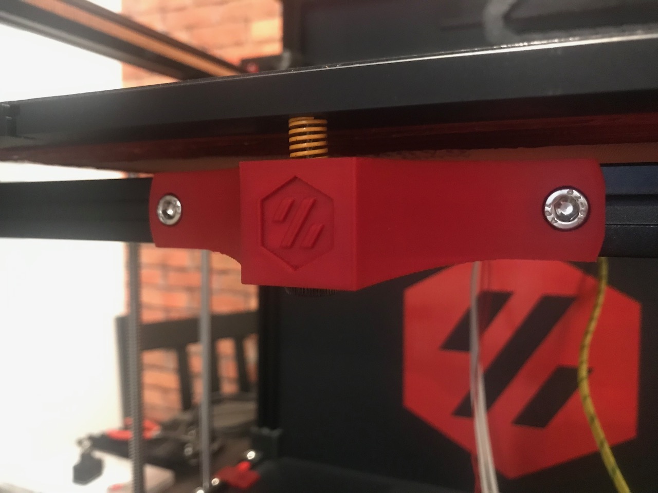
✅ Bed Mounting
Assembly
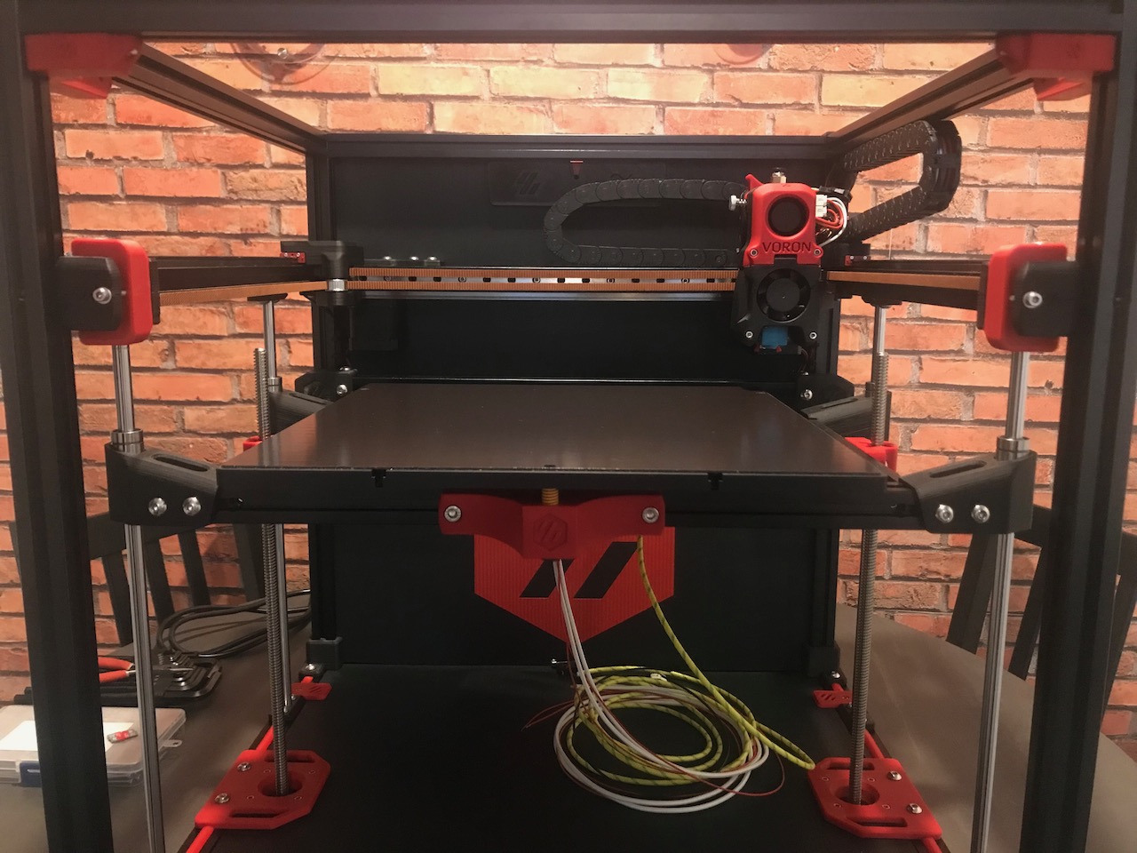
When mounting the bed, I noticed the mounting holes in the aluminum plate I purchased are a little different to the mounting holes in the Drawings, my rear bed mounting holes are about 265mm from the front rather than 262mm. I have redesigned the front bed mount move the front mounting hole forward a few millimeters to compensate
Parts Used
| Item | Quantity |
|---|---|
| M3 Knurled Nut (DIN 466-B) | 1 |
| M3x16 SHCS | 2 |
| M3x40 SHCS | 1 |
| M3 T-nut | 2 |
| M4 Knurled Nut (DIN 466-B) | 2 |
| M5x16 SHCS | 2 |
| Yellow Die Spring - M3 | 1 |
🔧 Wiring
Assembly
Parts Used
| Item | Quantity |
|---|---|
| High Temp Yellow/Green Fibreglass coated wire 2.5mm (m) | 1 |
| M3x8 SHCS | 2 |
| Red Ring Crimp Terminal | 1 |
| Thermal Fuse (125C) | 1 |
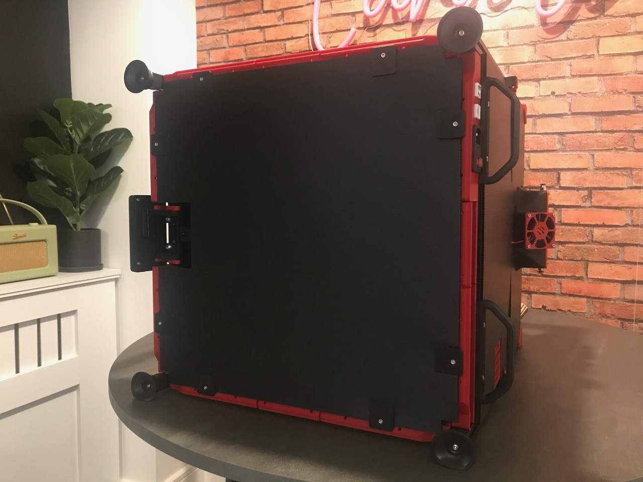
Panel Mounting
Image © 2020 Voron Design
🔧 Panel Mounts
| Item | Quantity | Material | Size | Weight | Cost | Printed | Notes |
|---|---|---|---|---|---|---|---|
| bottom_panel_clip | eSun ABS+ (Black) | 1.10m | 2.80g | £0.05 | ✔️ | This is a Trident Part | |
| 2 | eSun ABS+ (Black) | 1.58m | 4.04g | £0.08 | ✔️ | This is a Trident Part | |
| corner_panel_clip_4mm | 6 | eSun ABS+ (Fire Engine Red) | 1.12m | 2.87g | £0.05 | ✔️ | This is a Trident r1 Part |
| corner_panel_clip_6mm | 8 | eSun ABS+ (Fire Engine Red) | 1.60m | 4.07g | £0.08 | ✔️ | This is a Trident r1 Part |
| midspan_panel_clip_4mm | 6 | eSun ABS+ (Fire Engine Red) | 0.74m | 1.89g | £0.04 | ✔️ | This is a Trident r1 Part |
| midspan_panel_clip_6mm | 8 | eSun ABS+ (Fire Engine Red) | 1.04m | 2.66g | £0.05 | ✔️ | This is a Trident r1 Part |
| handle | 2 | ❌ | For Voron 2.2 Will replace with Sturdy Handles | ||||
| light_bar | 2 | eSun ABS+ (Black) | ❌ | This is a Switchwire Part. Will replace with LED Bar Clips |
NOTE: I have not been able to succesfully print the bottom panel hinges, they always seem to fuse up and the small pin just snaps when trying to free the hinge. I will print extra panel clips instead.
Assembly
Parts Used
| Item | Quantity |
|---|---|
| M3x8 SHCS | 26 |
| M3x12 SHCS | 24 |
| M3 Hammer Head T-nuts | 42 |
❎ Front Doors
| Item | Quantity | Material | Size | Weight | Cost | Printed | Notes |
|---|---|---|---|---|---|---|---|
| door_hinge | 6 | ❌ | Using 2 extra here like the Trident. Will swap for Clamping Door Hinges | ||||
| handle_bottom_left | 1 | eSun ABS+ (Fire Engine Red) | 1.62m | 4.14g | £0.08 | ✔️ | |
| handle_bottom_right | 1 | eSun ABS+ (Fire Engine Red) | 1.62m | 4.14g | £0.08 | ✔️ | |
| handle_top_left | 1 | eSun ABS+ (Fire Engine Red) | 1.42m | 3.61g | £0.07 | ✔️ | |
| handle_top_right | 1 | eSun ABS+ (Fire Engine Red) | 1.42m | 3.61g | £0.07 | ✔️ | |
| latch | 1 | eSun ABS+ (Black) | 1.28m | 3.26g | £0.06 | ✔️ |
Assembly
Parts Used
| Item | Quantity |
|---|---|
| 3M VHB Tape 5952 | 1 |
| 6x3mm Neodimium Magnet | 10 |
| M3 Hammer Head T-nuts | 1 |
| M3x8 SHCS | 1 |
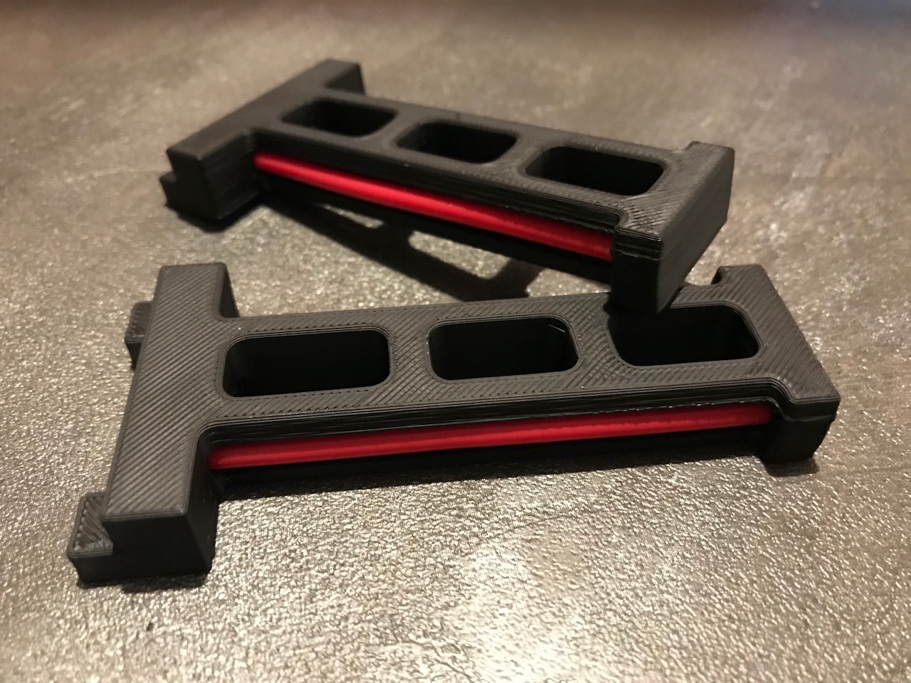
🔧 Spool Management
| Item | Quantity | Material | Size | Weight | Cost | Printed | Notes |
|---|---|---|---|---|---|---|---|
| bowen_retainer | 1 | ❌ | This is a Trident Part. Not printing this as I will be using the Smart Filament Sensor Mount | ||||
| spool_holder | 2 | eSun ABS+ (Black) | 6.07m | 15.47g | £0.29 | ✔️ | This is a Trident Part. May not print this as I currently use an eSun Filament Dryer box |
Assembly
Parts Used
| Item | Quantity |
|---|---|
| Red Bowden Tube (m) | 1 |
| M5 Hammer Head T-nuts | 2 |
| M5x16 BHCS | 2 |